Introduction to electronics
Inputs and outputs on a breadboard. Connecting inputs and outputs to a Microbit.
Prep for this week’s class
- If you’ve never done any electronics before, read an introductory tutorial or watch a video to get some of the basics:
- SparkFun have great tutorials
- Lots on YouTube, e.g. Beginner Electronics - YouTube
Formative assessment and project ideas
-
Present your work so far and offer help to others. More info
-
Suggest some project ideas, to inform content after Easter. Final 4 weeks will be self-directed. Lockdown ideas
This week:
- Tour of some basic components
- Circuit basics
- Connecting a circuit to a microcontroller
- Programming a microontroller to respond to input and do something with it
Electronics basics
Daniele Ingrassia presentation
Components
Breadboards
Essentially some short wires pre-set in a convenient configuration
- What’s significant and what isn’t on the breadboard
- Internal wiring

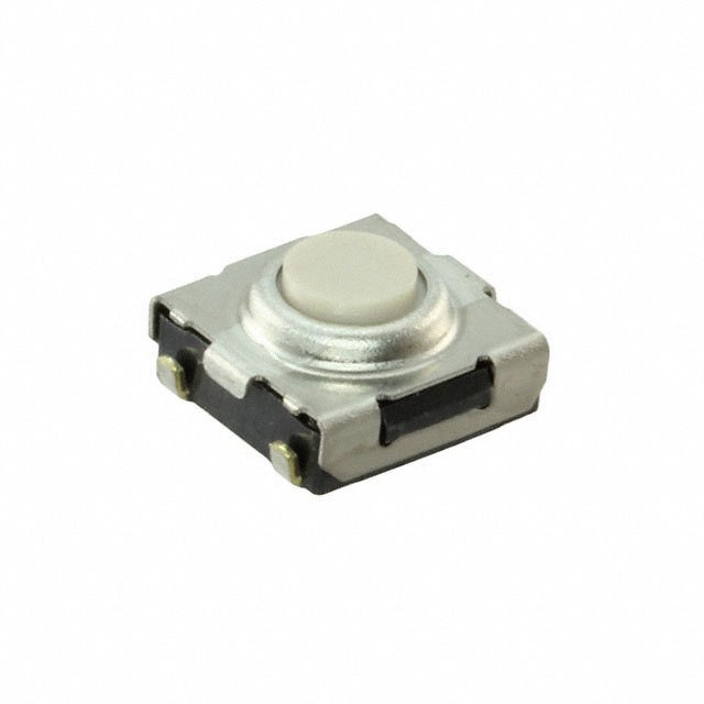
Buttons and Switches
Surface mount versions for circuits – picture
Momentary buttons - “N.O.” make a circuit when pressed (example use: connect a chip’s reset pin to GND)
You might want to use cool buttons for UI elements – picture
Resistors
- Value measured in Ohms (1 Ohm, 5 kOhm, 4k7 Ohm, etc.)
- Limit the flow of current
- Ohm’s law: I = V/R
Uses often include:
- Regulate current to LEDs – picture
- Keep pins high or low (pull-up/pull-down) without current flowing <!– Sizes:
- We use 1206 (0.12”× 0.06”)
- Hand solderable
- You can get a trace between the two ends –>
More: Resistors - learn.sparkfun.com
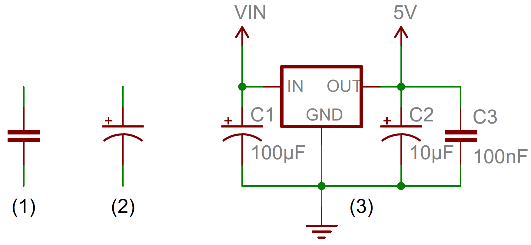
Capacitors
Store charge, and release it when the voltage across the cap reaches a specific level
Q (charge stored) = C (capacitance) x V (voltage across plates)
Value of capacitance (amount of charge it can store): Farad (F, nF, pF, uF, etc.)
Uses:
- Filtering high-frequency noise from ICs (“decoupling” or “bypass” capacitors)
- Supplying current to IC pins very quickly (e.g. when you ask it to switch on and off in your program)
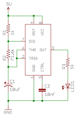
- Create pulses at specific time intervals (with resistors) <!– Sizes:
- 1206 SMD –>
- Bigger capacitors often polarised
More: https://learn.sparkfun.com/tutorials/capacitors
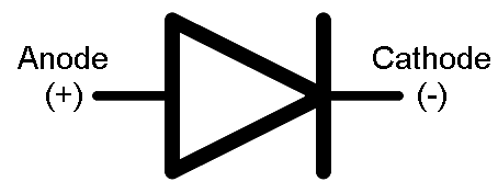
Diodes
Conducts only in one direction (as shown in circuit symbol)
Current flows from anode (+) to cathode (-) (alphabetical)
Uses:
- Prevent current going in the wrong direction (e.g. if you connect a battery backwards)
- Often used in AC/DC convertors
Types:
- Signal diode
- Specialised: Schottkey diode, Zener diode
- LED: emits light and happiness
Diodes are polarised: bar on the symbol is the same as on the package (cathode)
Diodes have no internal resistance, so can draw all the current available, and blow up
So use a current-limiting resistor (e.g. 100 Ohm, 1K Ohm) - very common with LEDs
Analog sensors
e.g.
- Tilt switches
- Hall effect sensors
- Bend sensors
- Accelerometers
- Capacitive sensors
- Temperature sensors
- Potentiometers
When you’re detecting something using an analog sensor and a Microbit (or Arduino) what you’re actually measuring is the voltage at the pin where you plug the sensor in.
The sensor itself usually changes resistance in response to some condition (heat, flex, humidity, magnetic force, etc.)
Most work by dividing a voltage by a variable amount (e.g. potentiometer). In some cases, you have to provide 0V and VCC (e.g. 3V or 5V) across the sensor to build your own voltage divider (e.g. for a flex sensor)
- Analog vs digital iputs and outputs
- Possible values
- Calibrating sensors - e.g. for wearables
Using External Inputs and Outputs (“IO”) with Microbit
![]() May need to split the class here. Some exercises could be done with onboard sensors in the simulator (focus on the coding).
May need to split the class here. Some exercises could be done with onboard sensors in the simulator (focus on the coding).
 Exercise: Light an LED with just 3V and GND pins
No coding required.
Consult the pinout to see which pins are 3V and GND.
Exercise: Light an LED with signal and GND pins
Write some code to send a digital high signal to one of the pins, and connect the LED between this pin and GND.
Digital value 1 = “high” = 3V
Note pinout diagram (of Microbit and of Breadboad connector)
- Note some pins interfere with LED Matrix
- back pins of connector do not go sequentially!
https://microbit.org/guide/hardware/pins/
pin 3 is shared with some of the LEDs on the screen of the BBC micro:bit, so if you are using the screen to scroll messages, you can’t use this pin as well.
Exercise: Make your LED flash
Can you change your code to switch the LED on and off?
Think of it as an animation that loops forever. You just need to control the timing.
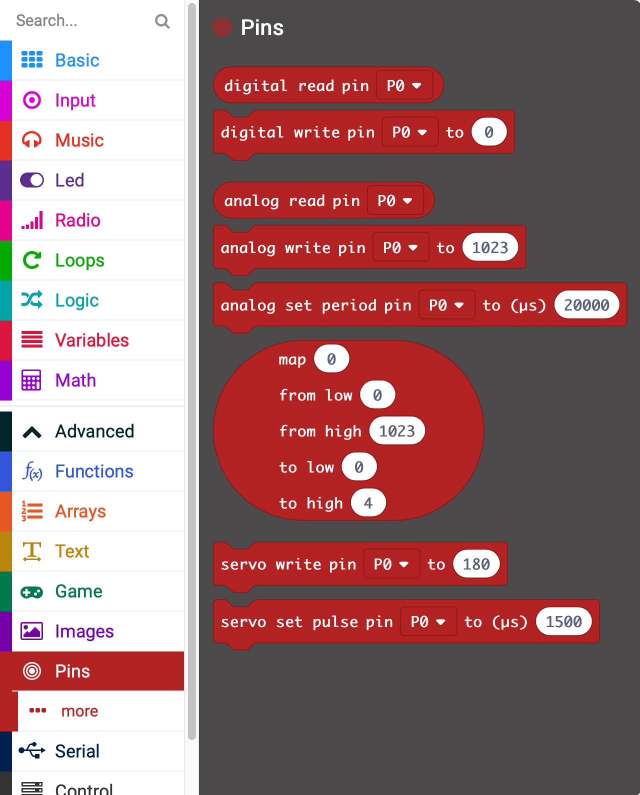
Exercise: Read an external input
![]() Possible in simulator by dragging over pins with your cursor.
Possible in simulator by dragging over pins with your cursor.
Connect an external sensor (or potentiometer) and read the value as it changes. Try:
- Displaying the value as a number on the LED matrix
- Printing it to the serial monitor
- Displaying a bar chart on the LED matrix
- Mapping the values to a 1-10 scale. What numbers can you get out of the sensor?
- Creating a threshold. Make the Microbit do something when the sensor goes beyond a set value.
Exercise: Connect a sensor or control and control an output
Combine inputs and outputs! e.g. change the speed your LED flashes by turning a knob
What you’ll need
- Microbit
- USB Cable
- Breadboard
-
Breadboard adapter
- External input: sensor, potentiometer, button
- External output: e.g. LED, OLED screen, LCD Screen, motor, buzzer, relay, servo
Only if you get stuck: my circuit diagram
Exercise: Go further
Try other sensors, e.g. environmental sensor, flex sensor
Some Potentiometer ideas and sketches
http://www.multiwingspan.co.uk/micro.php?page=pot
The potentiometer will give you a reading from 0 - 1023. If you divide that number by 4, you can use the reading to set the brightness of the LED matrix. You could draw a series of images. Turning the potentiometer could then allow the user to select or scroll through the images displayed on the LED matrix. Use some IF statements or the MAP block to convert your potentiometer reading into a number that you can use to move a sprite across one axis of the matrix. Add a second potentiometer and you have both directions. A potentiometer and buzzer can be used. Convert the potentiometer reading into a number that you can use to play a tone on the buzzer. Mix in some button action if you want to be able stop and start the buzzing freely
Write pot reading to console and to screen https://makecode.microbit.org/_7Ar65X3woDih
Switch LED on or off at threshold https://makecode.microbit.org/_dHrJxy14mYLy
Control 3 LED trafic lights with pot Code: https://makecode.microbit.org/_4LUCadhhsc79 Circuit: https://www.tinkercad.com/things/j3oedMc3CuT-microbit-io-pot-and-3-x-led
Other more advanced Microbit ideas
Once you can read an input and control and output you’ve got the basics of an interactive device. Most other projects are a variation of this.
Flex sensor
Only has 2 pins so you need to make a voltage divider.
Basic serial reading: https://makecode.microbit.org/_6KY8EF7CvV1D
Shows how to clean up data into useful range. But boring!
Neopixels and Flex sensor: https://makecode.microbit.org/_Kcog2V9WgEA3
Connect Microbits together
http://www.multiwingspan.co.uk/micro.php?page=bit2bit
Get input and send it to a phone
Bitty Datalogger app: https://www.bittysoftware.com/apps/bitty_data_logger.html
Further reading
Fab Academy:
- Input devices: http://academy.cba.mit.edu/classes/input_devices/index.html
- Output devices: http://academy.cba.mit.edu/classes/output_devices/index.html Electronics bible: Paul Horowitz, Winfield Hill-The Art of Electronics-Cambridge University Press (2015) Good hobbyist starting point: Charles Platt’s Electronics Pages: Books Available
Assignment
Use a breadboard, jumper wires and input and output devices to build an interactive device based around a Microbit. Program your Microbit to respond to input and produce an off-device output. If you find this easy, do something more ambitious!
If you only have access to the simulator, try some more advanced interactive examples using the onboard inputs and outputs.
Stuck for ideas of what do (how how to make it work)?
There are lots of tutorials. Try:
What do I need to do to pass? (40%)
Document all your work on your student blog, with photos and videos to show what you did, what went wrong, and how you fixed it.
Cite external sources where you have used someone else’s work.
Extra credit (50-100%)
- Replicate the circuit and program logic with an Arduino
- Use multiple input or output devices
- Create a higher fidelity prototype that could be embeded in a device or worn on clothing
Show your research and include reflection on the process, and other resources you have found.
For next week
Over Easter, research your final project:
- How could you make it?
- Sketch out ideas, look for inspiration from other projects, compile a mood board or list of references
- Do you need any special materials or parts that you need to source in advance?
- Are there any skills you need to start learning now?
You should be ready to start making (or have already started) by the time you come back after Easter.