Week 2: Computer-Aided Design (Solidworks)
Introducing parametric modelling.
Background information on CAD
Watch the corresponding Fab Academy lecture. We’ll be covering part of this content.
- Fab Academy lecture notes: http://academy.cba.mit.edu/classes/computer_design/index.html
- Lecture from 2019
Baseline
Who has:
- Used CAD software
- Used parametric software
- Produced 2D drawings
Solidworks (PC only)
is…
- Parametric: everything is driven/adjusted by numbers (length, diameter, thickness, colour, etc).
- Feature-based: geometry is created with features
- Associative: parts, assembles, drawings are linked - a change in one will filter to all
SW can do: FEA, CFD, motion analysis, electronic wiring, lots more!
Student licences- £6 for a USB from computer store, 1st Floor Watts Building. Renew at the start of each academic year.
Certification exams: we will provide these: TBA
Resources:
- Start with these…..Help menu > tutorials (Lesson1: parts, Lesson2: Assembles, Lesson3: drawings) - these are excellent, make notes, observe everything and master them.
- lesson 1: parts video, and here is the part to download
- lesson 2: assemblies video, and here is a .zip file with the assembly to download
- lesson 3: drawings video
- use the help (online also)
- Grabcad/Thingyverse/etc (filter for Solidworks models).
- any existing models to reverse engineer
- Lynda.com (for UoB: www.brighton.ac.uk/lynda) - Solidworks 20XX essentials.
- sketching exercises
- part modelling exercises
Layout:
Units: see bottom right hand corner (use millimeters!)
Navigation:
MIDDLE DOES EVERYTHING!
- zoom: scroll middle
- rotate: hold middle
- pan: hold middle + CTRL
File types:
- Parts: as it would be manufactured, and here is an example part to download
- Assemblies: a collection of parts (and/or of other sub-assemblies), and here is a .zip file with parts and an assembly file
- Drawings: orthographic of parts (with dimensions) and assemblies (with NO dimensions, with balloons + bill of materials (BOM))….or both.
difference between Fusion 360 and Solidworks
Basic part modelling process:
- Create new sketch
- Select plane or flat surface to sketch on
- Draw 2D sketch (open or closed)
- Exit sketch
- Use sketch to create feature
Follow these steps, be methodical
Sketch entities: (note different options for each)
- line
- arc
- rectangle
- circle
- spline (avoid where possible)
- use smart dimensions ALWAYS
- toggle construction lines on/off
Sketch tools:
- convert entities
- offset entities
- trim (oh power trim!!)
- mirror/pattern
Sketch relations:
- coincident
- concentric
- equal
- parallel
- perpendicular
- colinear
- coradial
Basic features:
- extrude/cut
- revolve/cut
- hole wizard Intermediate features:
- sweep/cut
- loft/cut
- pattern
- mirror
Early part challenge:
- create a 6-sided die (10x10x10mm, R1mm fillets on all faces, D2mm holes 0.5mm deep (opposing sides add up to 7)
- all details must be dimensioned fully
- approach this in different ways, aim to do it as fast as you can
- record < 1min, excellent < 5min, ok < 15min
- 2019 leaderboard
- example die part file to download
Second part challenge:
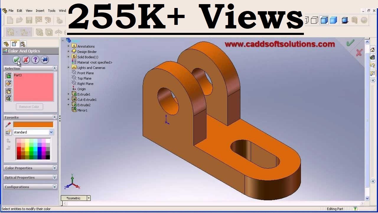
- create a bicycle stem using extrude/cut, fillets. You don’t need to create extra planes, but you can if you wish.
- this is an exercise in understanding how to use your reference geometry (planes) well - it is quite a spacial awareness challenge!
- here is a completed version with all the trimmings
- start with the three basic cylinders, then add details after.
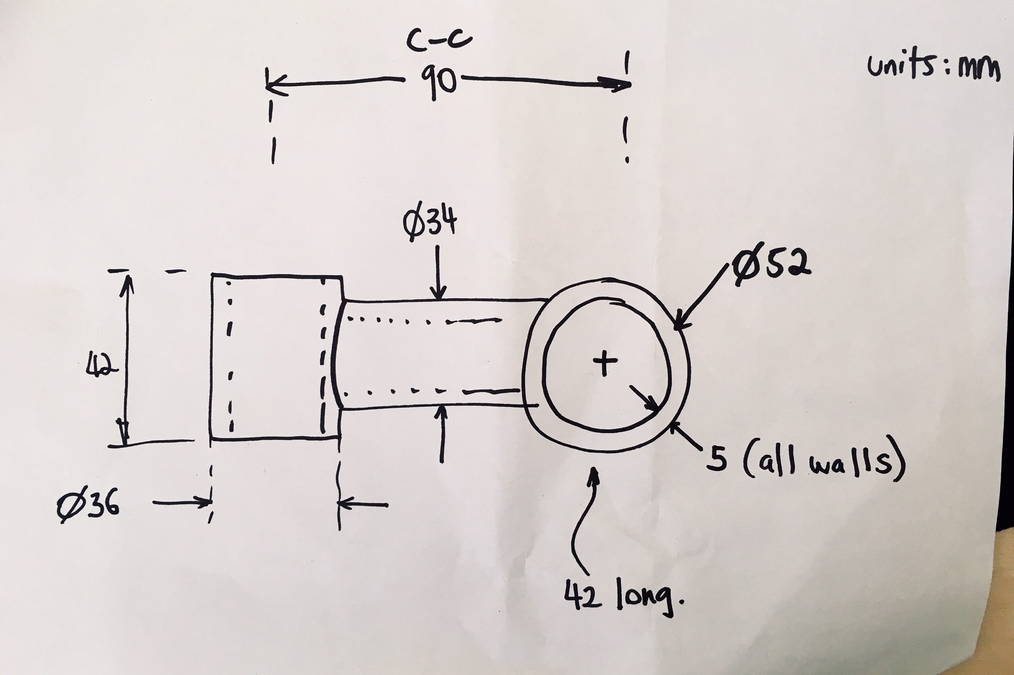
- for an extra challenge, angle the head tube (vertical tube) by 7 degrees to the horizontal
Useful tools:
- toolbox (nuts, bolts, gears etc)
- Traceparts CAD models
- also Grabcad/Thingyverse/etc
Assemblies
- can mate: vertices, lines/centrelines, faces, planes
- coincident, offset, parallel, concentric etc
- standard mates
- advanced mates: limits
- mechanical mate: gears
- mechanical mate: cams
- mechanical mate: belt+pully
- exploded and collapsed views
- animations: rotate, explode, collapse
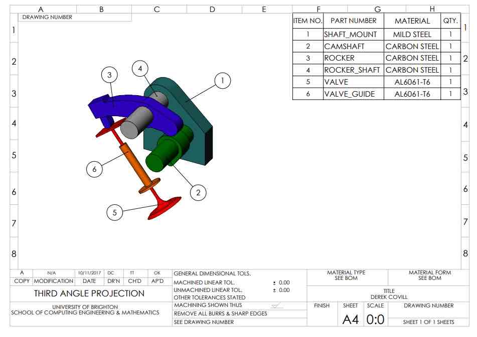
Assembly challenge
- download this .zip folder and unzip it
- open the “plunger.asm” assembly file
- look at how the parts move
- here is an assembly drawing to act as a guide
- the challenge: recreate this assembly in a new assembly file. Create an exploded view and animate the explode/collapse.
- bonus: position the link plunger so that it is 15degrees to the horizontal. This will lock the assembly so it won’t move.
Drawings
Rules
- make it clear!
- use only enough views as are necessary
- don’t duplicate dimensions
- make dimensions measurable (using ruler, calipers, micrometer etc)
- don’t cross dimensions
- space dimensions consistently
- don’t place dimensions on a part
- make sure the title block is complete
- use sans serif fonts only (ideally use CAPS)
Tutorial
- Help menu > tutorials (Lesson3: drawings)
- lesson 3: drawings video
- advanced tutorials: - Help menu > tutorials (all) > Advanced drawings (a.Drawing views, b. Detailing, c. Assembly Drawing views)
-
orthographic drawings of parts (with dimensions). Note that there should be sufficient detail and dimensions for the part to be manufactured. Drawings should be checked by others.
-
assembly drawings have NO dimensions, but they do have balloons and include bill of materials (BOM)
- you can also combine both types of drawings into a single drawing, but this is not advised. both-part-assembly-drw-combined.
- introduction to technical drawing
- types of views
- BS 8888:2017 –Technical product documentation and specification
- include appropriate tolerances simple tolerances drw
- base tolerances on manufacturing capability charts
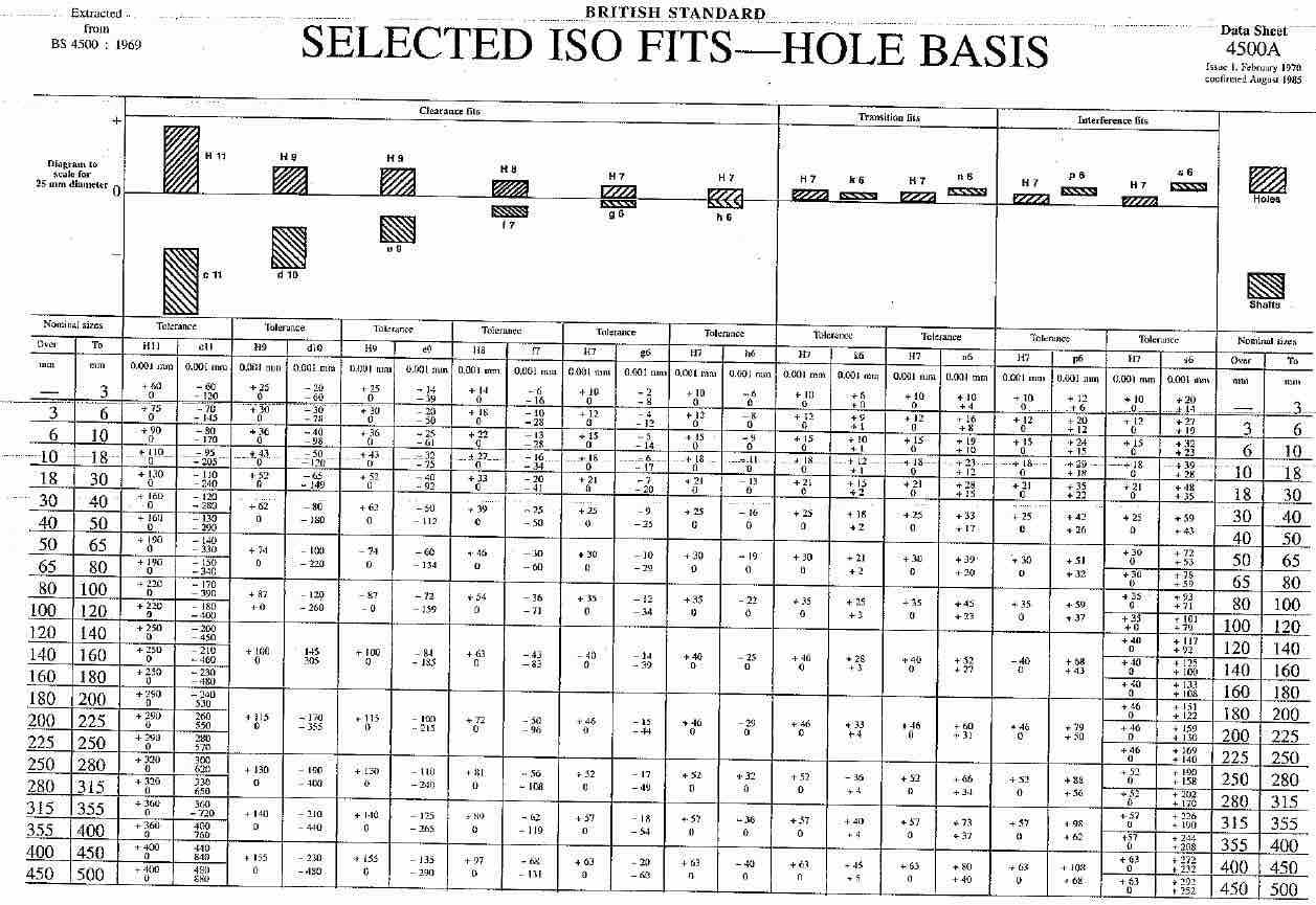
- limits and fits tolerances for holes and shafts
- use the solidworks A4 drawing template
- 1st (roll) or 3rd (slide) angle projection video
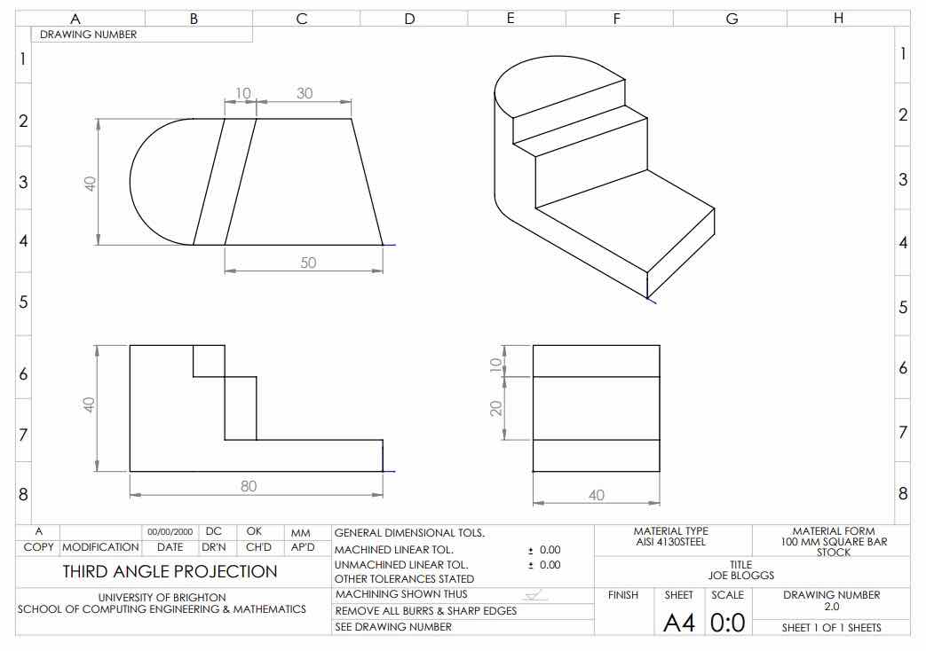
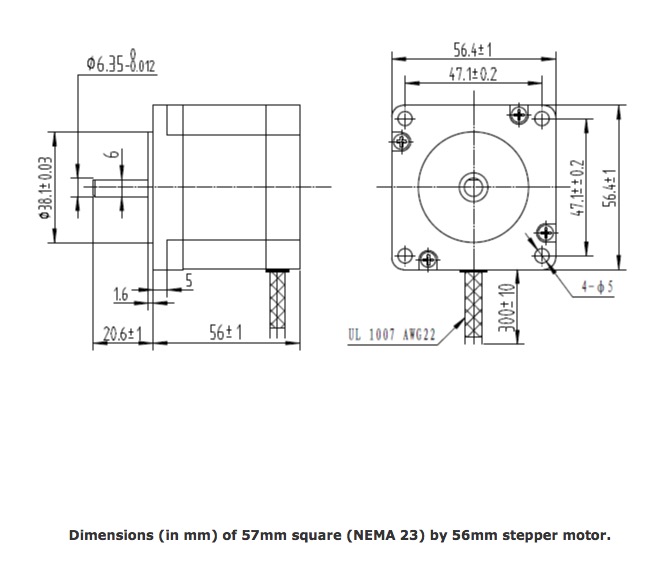
Part drawing challenge
- here are some good exercises to help understand technical drawings
- pick one of these, create the part then create a complete drawing for this part (assume one square = 10mm)
- use the template provided above
- include all dimensions required to make the part
- include a complete title block
- assume that it is machined using a CNC milling machine and then specify the appropriate tolerances using the manufacturing process capability charts above
Assembly drawing challenge
- find an interesting assembly in GrabCAD (make sure it’s a Solidworks assembly!) and download it
- unzip the folder with all the files
- make a complete assembly drawing of the main assembly
- use the template provided above
- include a complete title block
- include baloons for all parts
- include a complete/appropriate BOM (note that you may need to make adjustments to part names or other details)
Advanced part drawing challenge for homework
- Lego part challenge: download the lego solidworks part here
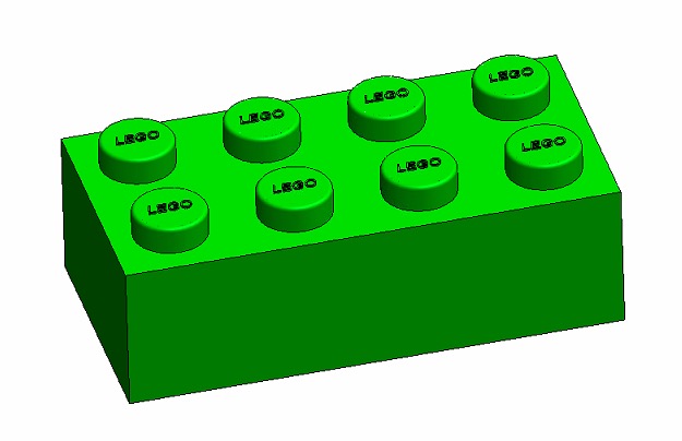
- create a part drawing of this lego brick
- use the template provided above
- include all dimensions required to make the part
- include a complete title block
- note the requirements for this to be a
- assume that it is injection moulded from ABS and then specify the appropriate tolerances using the manufacturing process capability charts above
- assume that the bosses of the lego brick need to be a ‘press fit’ with the underside of the next brick, using a H7/p6 tolerance which assumes H7 (hole) tolerance range = +0.000 mm to +0.025 mm, and p6 (shaft) tolerance range = +0.042 mm to +0.026 mm
- note…this is challenging :0)
More features in Solidworks
- features: extrude, hole wizard, mirror, pattern, shell, fillet, revolve, sweep, loft, split
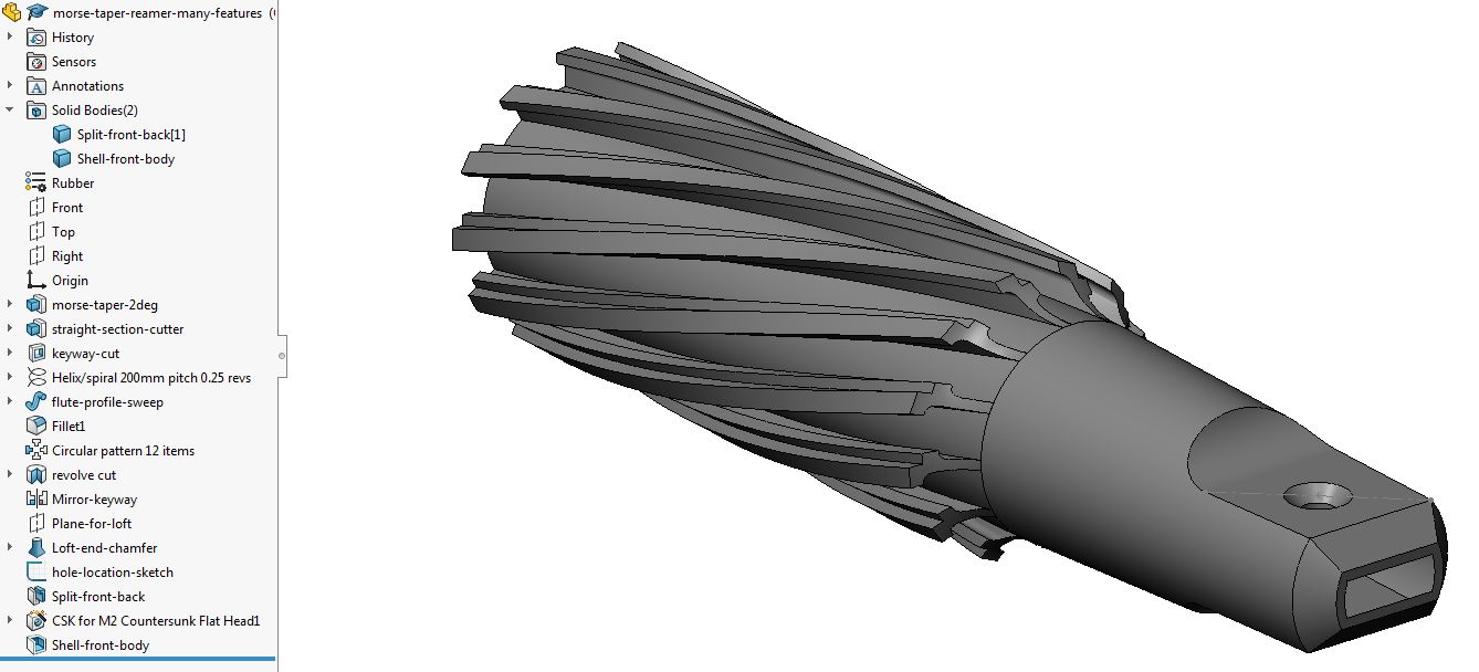
- reamer part with many features
- Help menu > tutorials (All) > Revolves and Sweeps, Lofts, Patterns, Fillets)
Solidworks part features exam! (1 hour)
- Make a donut (overall diameter 100mm, section diameter 20mm) using a revolve (10 marks)
- Put a M5 countersunk hole through the donut (in axial direction) (5 marks)
- Pattern this hole so that there are 5 of them spaced around the donut (5 marks)
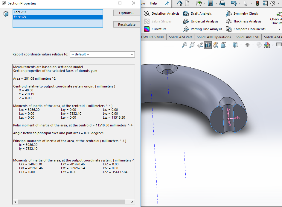
- Take a measurement of the cross sectional area of one cut through the donut where an M5 hole is (5 marks)
- In the same part make the same donut (no holes this time) again using a sweep (position it next to the existing feature) (10 marks)
- Now make it using a loft! Again, position it next to the existing parts (15 marks)
- Score out of 50? (Pass >= 25, merit >=35, distinction >= 45)
- here’s the finished part with the donuts!
- here’s the section view results
3D sketching in solidworks
- first a little warmup! let’s make this 2D sketch, and then make this solid part
- if you like that sketching exercise, here is 99 more!
- until now we’ve avoided 3D sketches because they can limit the ability to do features (e.g. revolve, loft)
- but they can also open up new ways to create geometry
- they work by creating a sketch that moves between sketching planes (e.g xy, yz, xz and any planes parallel to them) - and this is done by pressing TAB
- you can then draw lines in and out of these planes as we’ll see in this example
- 3d-sketched-rack-part
- this example is also done as part of the tutorial in Help menu > tutorials > 3d sketching