Week 2: Computer-Aided Design (Fusion 360)
Introducing parametric modelling.
Prep for this week’s class
Watch the corresponding Fab Academy lecture. We’ll be covering part of this content.
- Fab Academy lecture notes: http://academy.cba.mit.edu/classes/computer_design/index.html
- Lecture from 2019
Baseline
Who has:
- Used CAD software
- Used parametric software
- Produced 2D drawings
Outline for XE404
- Admin: Register, bring laptops
- Continuous assessment page on website (green/amber/red weekly table)
- Call up each week
- Repository of websites - let’s review
- Go see fablab + meet Kelly + Andrew
- 16.67 hours per week
- CAD + Fusion 360…
Fusion 360 (PC+Mac compatible, cloud based)
is…
- Parametric: everything is driven by numbers (length, diameter, thickness, colour, etc).
- Feature-based: geometry is created with features
- Associative: parts, assembles, drawings are linked - a change in one will filter to all
Fusion 360 can do: FEA, animation, CAM, link with Eagle (electronics design), lots more!
Introductory videos:
Start with these…..
- part 1: box component
- part 2: lid component and assembly
- part 3: complex lid detail + McMaster Carr-toolbox
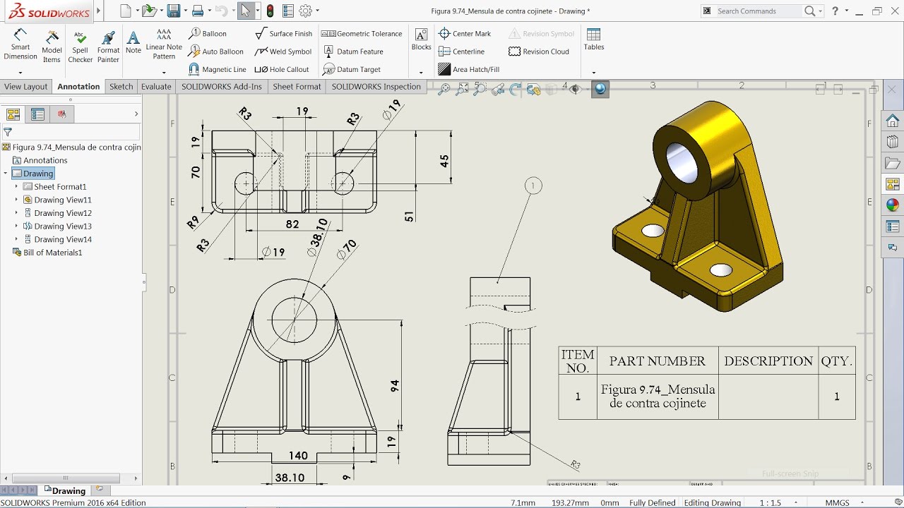
- part 4: drawings
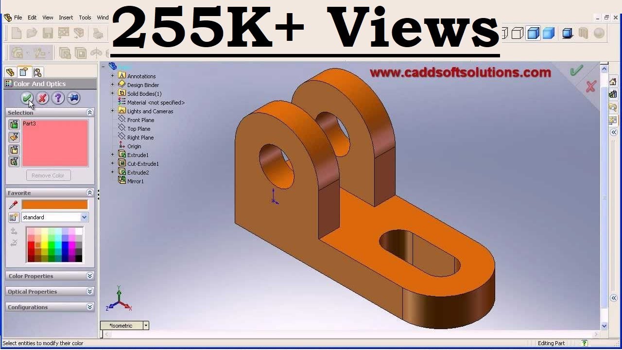
- part 5: adding colour to bodies/surfaces
Other resources:
- Autodesk videos
- Lynda videos how in LindedIn learning, access these through https://www.brighton.ac.uk/lynda
- Fusion 360 gallery of models
- Grabcad/Thingyverse/etc (filter for Fusion 360 models).
- any existing models to reverse engineer
Some material to practice on:
Layout:
Units: see document settings in the feature tree, use millimeters!
Navigation:
Use mouse shortcuts to zoom in and out, pan, and orbit the view of the model.
- Zoom in and out: Scroll the mouse wheel forward and backward.
- Pan: Left-click and hold, then drag.
- Orbit: Hold the Shift key, click and hold the middle mouse button, then drag.
- Zoom Extents: Double-click the middle mouse button.
File models:
- Components: as it would be manufactured
- Assemblies: a collection of components put together (and/or of other sub-assemblies)
- Drawings: orthographic of parts (with dimensions) and assemblies (with NO dimensions, with balloons + bill of materials (BOM))….or both
difference between Fusion 360 and Solidworks
Basic part modelling process:
- Create new sketch
- Select plane or flat surface to sketch on
- Draw 2D sketch (open or closed)
- Exit sketch
- Use sketch to create feature
Follow these steps, be methodical
Sketch entities: (note different options for each)
- line
- arc
- rectangle
- circle
- spline (avoid where possible)
- use smart dimensions ALWAYS
Sketch tools:
- extend
- offset
- trim
- fillet
- mirror/pattern
Sketch relations:
- coincident
- concentric
- equal
- parallel
- perpendicular
- colinear
- coradial
Basic features:
- extrude/cut
- revolve/cut
- hole wizard Intermediate features:
- sweep/cut
- loft/cut
- pattern
- mirror
Early challenge:
- create a 6-sided die (10x10x10mm, R1mm fillets on all faces, D2mm holes 0.5mm deep (opposing sides add up to 7)
- all details must be dimensioned fully
- approach this in different ways, aim to do it as fast as you can
- record < 1min, excellent < 5min, ok < 15min
- here’s an example completed component
Useful tools:
- toolbox (nuts, bolts, gears etc)
- Traceparts CAD models
- also Grabcad/Thingyverse/etc
- 1st or 3rd angle projection?
- technical drawing guide
Assignment
Design a 100x100mm tile part (SW or Fusion), colour it.
What do I need to do to pass?
- Use parametric CAD software to design a tile part that is dimensioned correctly
- Document all your work on your student blog, with photos/screengrabs and videos to show what you did, what went wrong, and how you fixed it. Make sure you include a final hero shot of the final outcomes. Cite external sources where you have used someone else’s work.
Extra credit
Assemble 9 of them as a pattern of 3x3 then create a drawing (A4 or A3) of your tile part with sufficient detail for it to be manufactured by someone else.
For the super keen (or those with previous parametric experience)
Design a male mould tool to make female mould tool, show as exploded assembly of the 3 parts (male mould tool + female mould tool + part)