Week 4: Electronics production
Making our first circuit board.
Prep for this week’s class
Watch the corresponding Fab Academy lecture. We’ll be covering part of this content.
- Fab Academy lecture notes: http://academy.cba.mit.edu/classes/electronics_production/index.html
- Lecture from 2018 (Fab-20180214D_Lesson04, the second video on the page): Fab-20180214D_Lesson04 Recordings
If you like, watch this short YouTube playlist showing the wole milling process.
Baseline
Who has:
- Made something with electronics?
- Used a CNC machine of any kind?
You don’t need to know any electronics this week.
We’ll start by producing a board, before we do design - you may not understand what the parts are, or why they are connected this way, we’re just learning how to put it together.
How to make a circuit
Just need a way to support and connect all the electrical components:
- Jumper wires and crocodile clips (not useful for any level of complexity)
- Conductive thread sewn into garments (good for components, but not for microcontrollers)
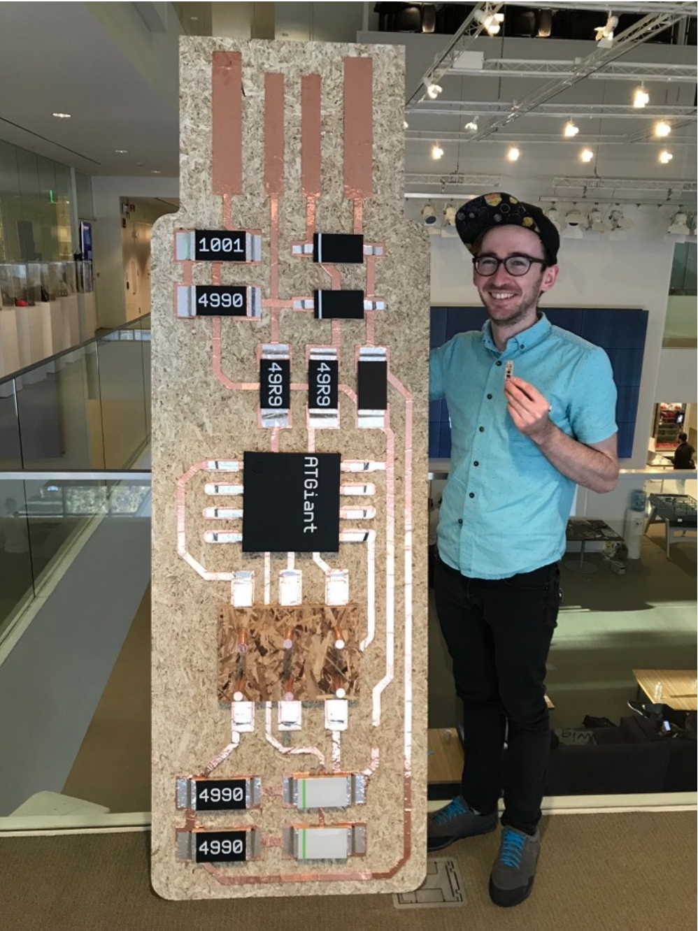
- Copper tape cut with the vinyl cutter, stuck to anything (giant programmer / picture)
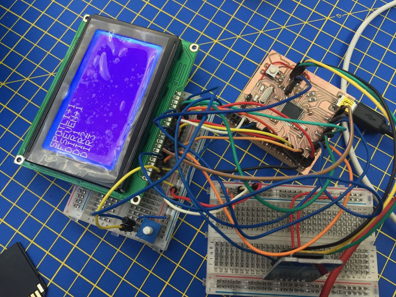
- Breadboards (picture) (unreliable, not scalable, a first step only - even on milled boards, you can edit afterwards)
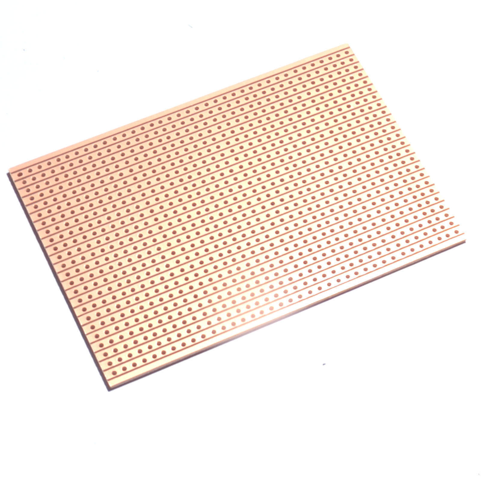
- Stripboard (picture) (like the inside of a breadboard, needs soldering)
- PCBs (printed circuit boards)
Making PCBs
Most are made from copper laminated onto a non-conductive substrate, and then copper selectively removed to form traces, pads, vias, etc.
Etching
Commercial process, hobbyist/prototyping level
- Uses nasty chemicals, safe disposal is non-trivial
- You must manage the lifecycle
Milling
How we do it.
Great for prototyping - every board can be different.
Not so good for batch production - slower than etching.
Move a tool bit around removing copper to leave circuit behind.
Video series of whole process
The Milling Machine
Roland MODELA MDX-50 Benchtop CNC Mill
Accuracy:
- positioning (< 1/1000”)
- tolerances (approx. 1/1000)
- e.g. bit size for traces: 0.3mm diameter
Tools
- Cutting outline of board (1mm diameter)
- Cutting traces (0.3 or 0.4mm diameter)
Tools are a consumable - maybe make 20 boards/tool if used properly.
Hard but brittle - don’t drop or knock.
Materials
FR1 - paper-reinforced (not FR4, which is glass-based)
Scaling up
The desktop mill is good for 1-10 boards.
What if you want to make loads of boards for an art project or small product run?
- Board houses can mill boards, but also stuff, or even source components, and fabricate.
- Or go to Shenzhen (or go through an online intermediary).
Design rules
Consider the machine, tools, materials and process when designing your circuit (next week).
- Machine has a level of stability ( = accuracy)
- Tools are round (how to cut a right angle?)
- Tools have a thickness (how close can traces be?)
- Neil: 15mil (mil = 1/1000 of an inch, not millimetre - see Eagle)
- Some tools are conical, so diameter varies (what if your board or bed isn’t flat?)
Our process
See the board milling guide
Now we have the traces on a board. What next?
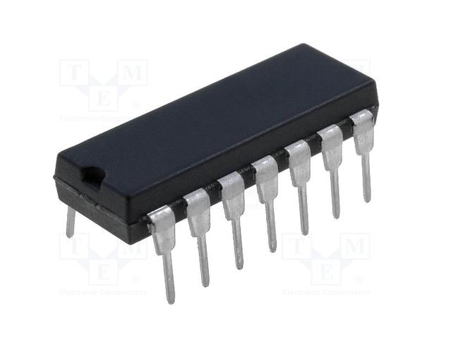
Components
Through-hole - picture
Often used by hobbyists - not us. Becoming obsolete.
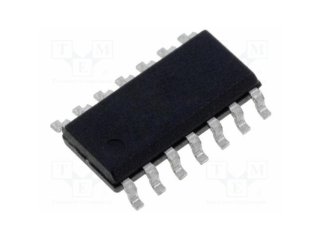
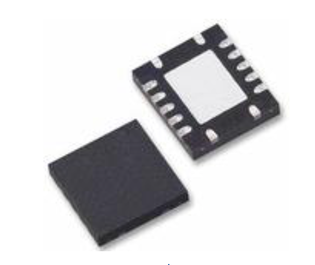
See also the components guide for the FabTinyISP Programmer
Soldering
Guide: Adafruit Guide To Excellent Soldering
Videos:
SMD Soldering - the easy way - YouTube (Arthur Guy)
EEVblog #186 - Soldering Tutorial Part 3 - Surface Mount (enthusiastic Aussie, unavoidable)
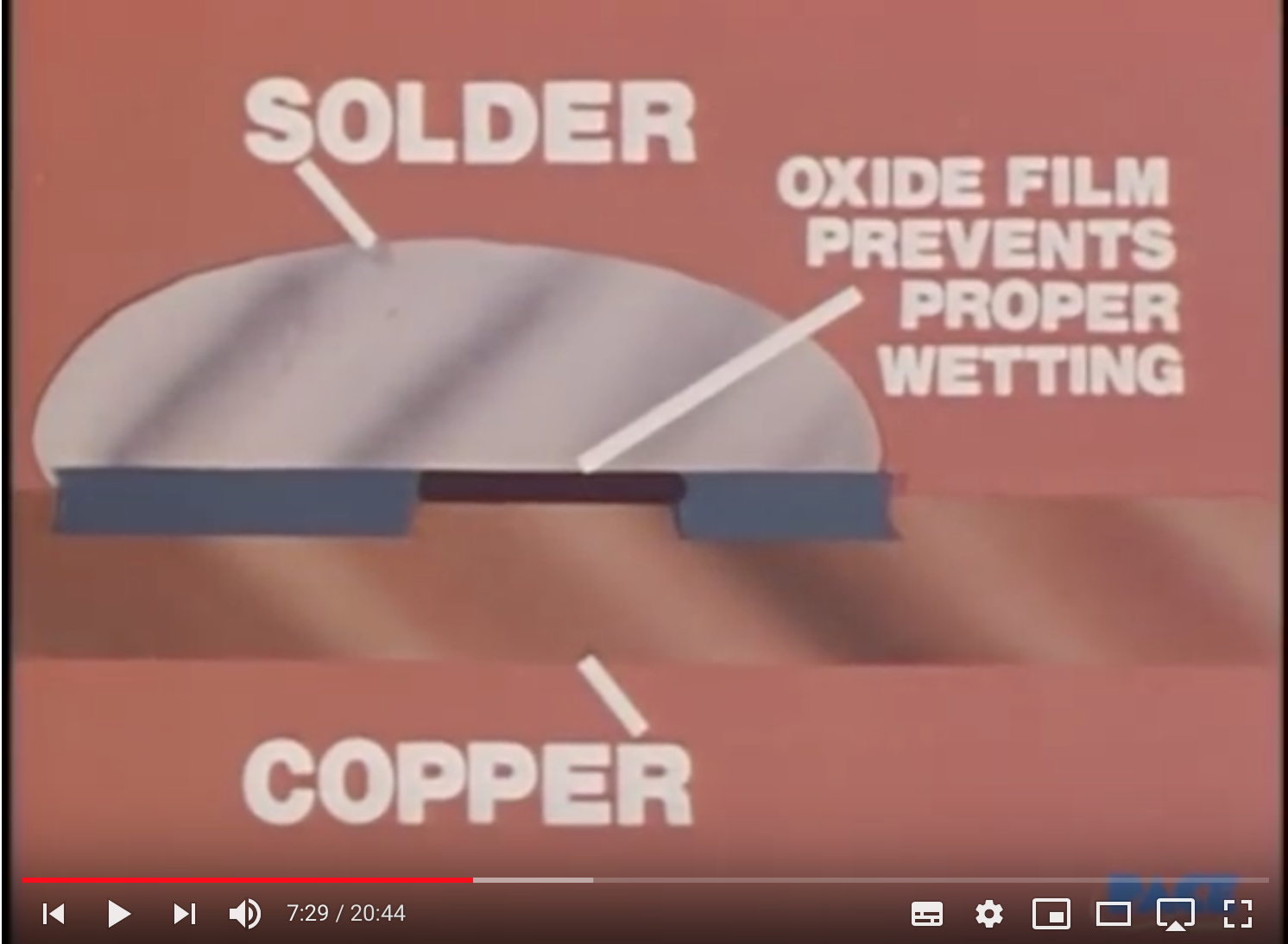
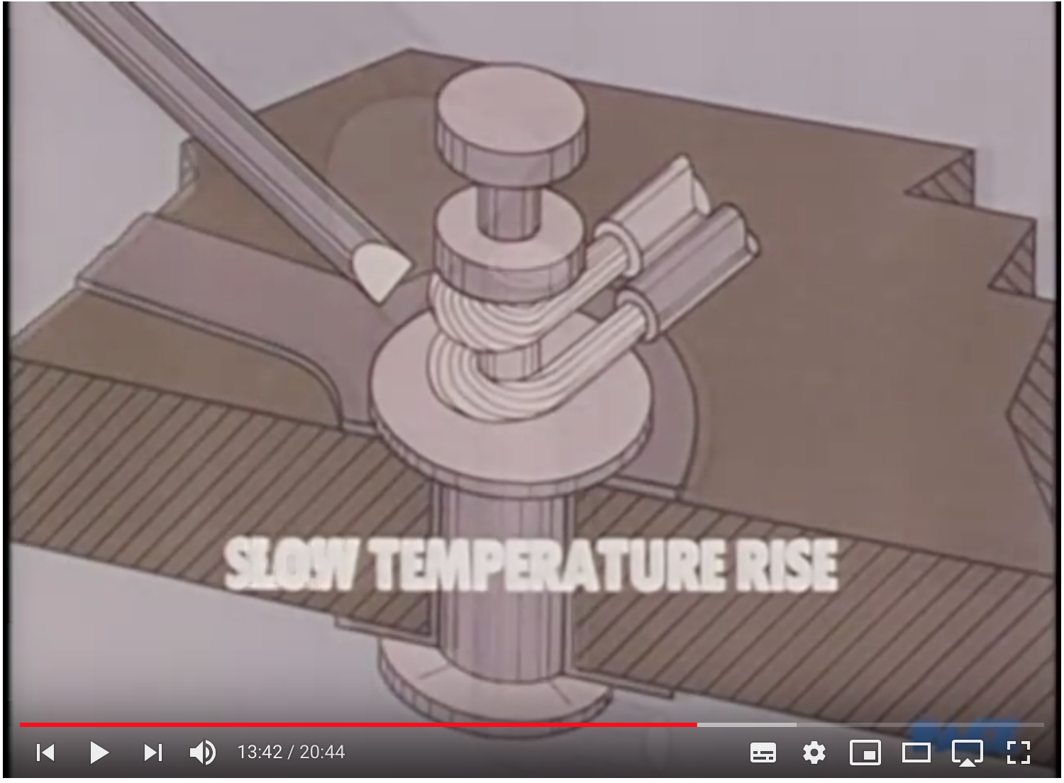
Basic Soldering Lesson 1 - “Solder & Flux” (excellent retro series, especially this video on materials: copper, solder and flux and how they work: e.g. clean copper,
thermal mass)
Remember:
- Clean your board to remove copper oxide and finger oils
- Keep soldering iron tip shiny and clean
- Switch the iron off when you’re not using it
- Don’t be tempted to use too high a temperature (that is not why your solder isn’t melting)
- Melting solder wets the joints
- Heat both parts of the joint with the iron
- Feed in small amount of solder - helps conduct heat
- Wait – learn to see the signs of a good flow and joint forming
- Once parts are at the right temperature, more solder will flow up and down parts
- Wait, then remove iron
- Check your work – you want shiny, smooth joints
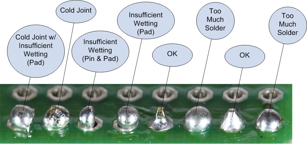
Recognising a bad joint
Common Soldering Problems - Adafruit Guide To Excellent Soldering
Techniques
Holding the board
- Tape
- Vice
Holding the part
- Tacking
- Note orientation of chips, capacitors, diodes, etc.
- Order of stuffing - inside out
Desoldering
- Braid - tin the braid first to help heat flow
- Pump
- Hot air gun - use directional tip (plus tweezers and gravity). Clean up with braid afterwards.
Safety
Fumes - an issue if you’re soldering for several hours
Leaded solder - Wash your hands!
Assignment
Mill and stuff an ISP programmer. Follow this design and instructions: Building the FabTinyISP
To really verify that is works, load the board with the programming software.
(What is an ISP programmer, and why do I need one?)
What do I need to do to pass?
Mill and stuff a board that passes a visual inspection (good traces, viable solder joints, correct components in the right places).
(See the components guide for the FabTinyISP Programmer)
(If there isn’t enough time for everyone to mill a board, we may do this in batches.)
Document all your work on your student blog, with photos and videos to show what you did, what went wrong, and how you fixed it. Cite external sources where you have used someone else’s work.
Extra credit
- Mill a board and teach someone else how to operate the machine
- Test the board you make with oscilloscope or the multimeter and document what you find
- Test that the board really works by verifying it does what it’s supposed to do (i.e. accept a program loaded onto it)
For next week
You will need access to a functioning programmer for next week.
Ideally, it should be one that you have made.
Materials we need this week
- Cutting files for programmer: http://fab.cba.mit.edu/classes/863.16/doc/projects/ftsmin/index.html
- FR1 for milling
- Some pre-milled boards WIP: make these
- USB extension cables (for USB key-style programmer boards)
- Components:
- 1x ATtiny45 or ATtiny85
- 2x 1kΩ resistors
- 2x 499Ω resistors
- 2x 49Ω resistors
- 2x 3.3v zener diodes
- 1x red LED
- 1x green LED
- 1x 100nF capacitor
- 1x 2x3 pin header
Failsafe for next week
Make some working programmers so students can use them to program their boards