Week 5: Electronics design
Designing, building and testing a circuit
Prep for this week’s class
- Installed and licensed Autodesk Eagle software: Free Software for Students & Educators
- Verified that you can open up and use the software.
- Having difficulty getting the educational version? Try the free hobbyist version
- Watch the corresponding Fab Academy lecture. We’ll be covering part of this content:
- Fab Academy lecture notes: http://academy.cba.mit.edu/classes/electronics_design/index.html
- Lecture from 2018: Fab-20180228D_Lesson06: electronics design
- If you’ve never done any electronics before, read an introductory tutorial or watch a video to get some of the basics:
- SparkFun have great tutorials
- Lots on YouTube, e.g. Beginner Electronics - YouTube
Baseline
Who has:
- Made something with electronics?
- Used an Arduino?
This week:
- Tour of some basic components
- Learn how to draw a circuit in Eagle
- Assignment: draw a circuit board, ready for milling (ending up where we started last week).
- (Make and test it)
- Next week, program it
Components
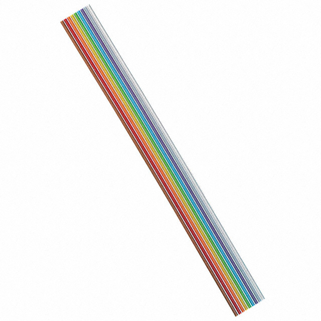
Wire
Ribbon cable used for ISP headers - and post-milling board edits – picture
Also, headers (mechanical convenience)
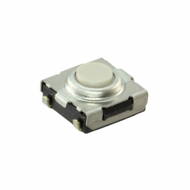
Buttons
Surface mount versions for circuits – picture
Momentary buttons - “N.O.” make a circuit when pressed (example use: connect a chip’s reset pin to GND)
You might want to use cool buttons for UI elements – picture
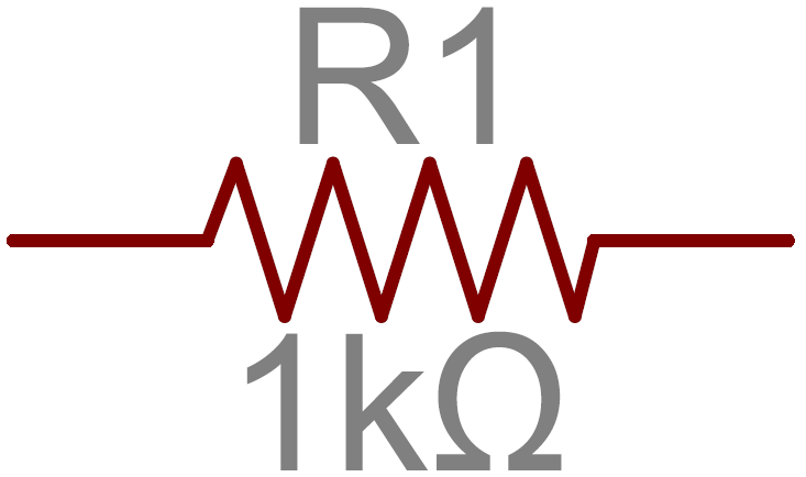
Resistors
- Value measured in Ohms (1 Ohm, 5 kOhm, 4k7 Ohm, etc.)
- Limit the flow of current
- Ohm’s law: I = V/R
Uses often include:
- Regulate current to LEDs – picture
- Keep pins high or low (pull-up/pull-down) without current flowing
Sizes:
- We use 1206 (0.12”× 0.06”)
- Hand solderable
- You can get a trace between the two ends
More: Resistors - learn.sparkfun.com
Capacitors
Store charge, and release it when the voltage across the cap reaches a specific level
Q (charge stored) = C (capacitance) x V (voltage across plates)
Value of capacitance (amount of charge it can store): Farad (F, nF, pF, uF, etc.)
Uses:
- Filtering high-frequency noise from ICs (“decoupling” or “bypass” capacitors)
- Supplying current to IC pins very quickly (e.g. when you ask it to switch on and off in your program)
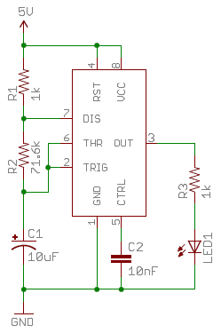
- Create pulses at specific time intervals (with resistors)
Sizes:
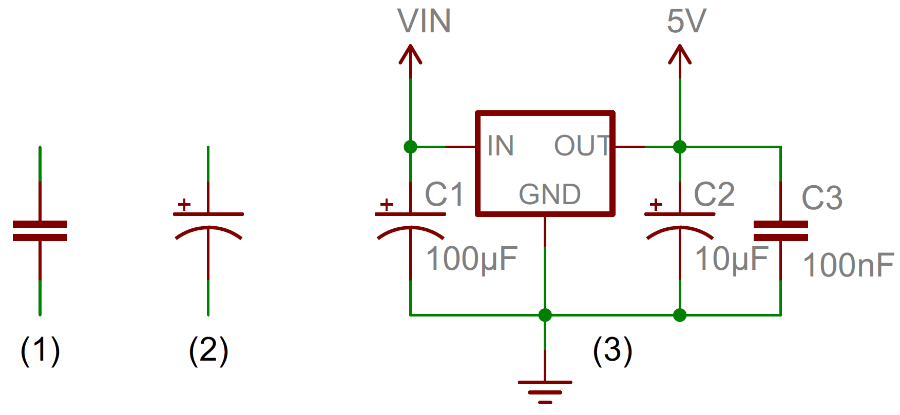
- 1206 SMD
- Bigger capacitors often polarised
More: https://learn.sparkfun.com/tutorials/capacitors
Crystals and resonators
Used to tell time.
Crystals are very accurate, but need 2 capacitors.
Resonators are more convenient, but less accurate (could cause problems for your IC, e.g. for fast serial comms).
IMHO: crystals are easier to solder, even with caps
Uses:
- External clock for microcontroller (IC)
Diodes
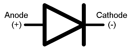
Conducts only in one direction (as shown in circuit symbol)
Current flows from anode (+) to cathode (-) (alphabetical)
Uses:
- Prevent current going in the wrong direction (e.g. if you connect a battery backwards)
- Often used in AC/DC convertors
Types:
- Signal diode
- Specialised: Schottkey diode, Zener diode
- LED: emits light and happiness
Diodes are polarised: bar on the symbol is the same as on the package (cathode)
Diodes have no internal resistance, so can draw all the current available, and blow up
So use a current-limiting resistor (e.g. 100 Ohm, 1K Ohm) - very common with LEDs
Microcontrollers
A whole circuit inside one package: a computer, analogy to digital convertors, clock, PWM outputs, memory, switches, etc, etc.
We’ll mostly use ones from Atmel:
- ATtiny 44/45, 84/85
- ATmega 328p (Arduino Uno)
- ATmega 32u4 (Arduino Leonardo, USB)
Datasheets - learn to love them!
And many more …
Further reading
Fab Academy:
- Input devices: http://academy.cba.mit.edu/classes/input_devices/index.html
- Output devices: http://academy.cba.mit.edu/classes/output_devices/index.html Electronics bible: Paul Horowitz, Winfield Hill-The Art of Electronics-Cambridge University Press (2015) Good hobbyist starting point: Charles Platt’s Electronics Pages: Books Available
Drawing circuits
Overview of Eagle
See the Detailed guide for more Eagle tips.
Libraries of parts
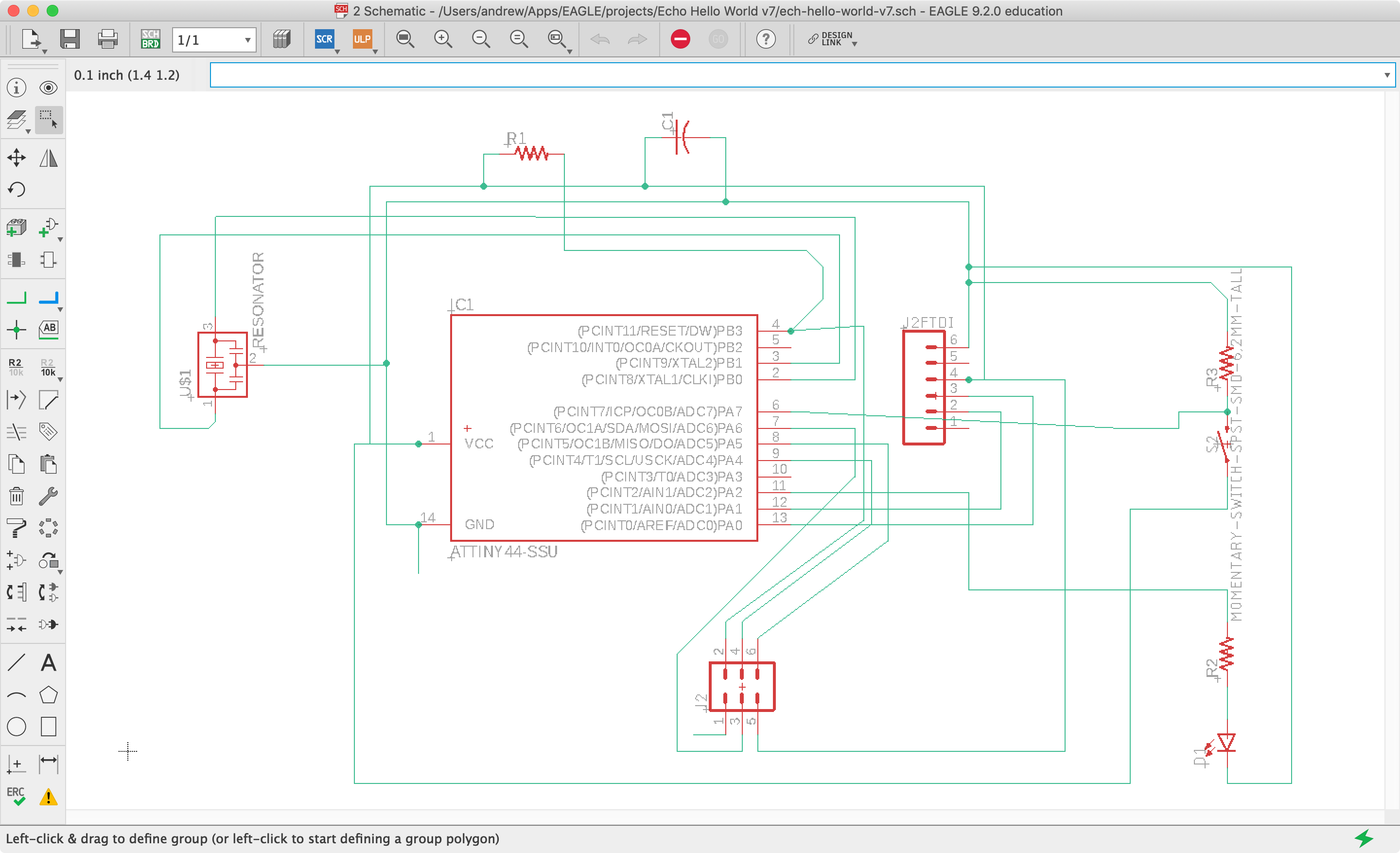
Schematic
Logical structure of a circuit.
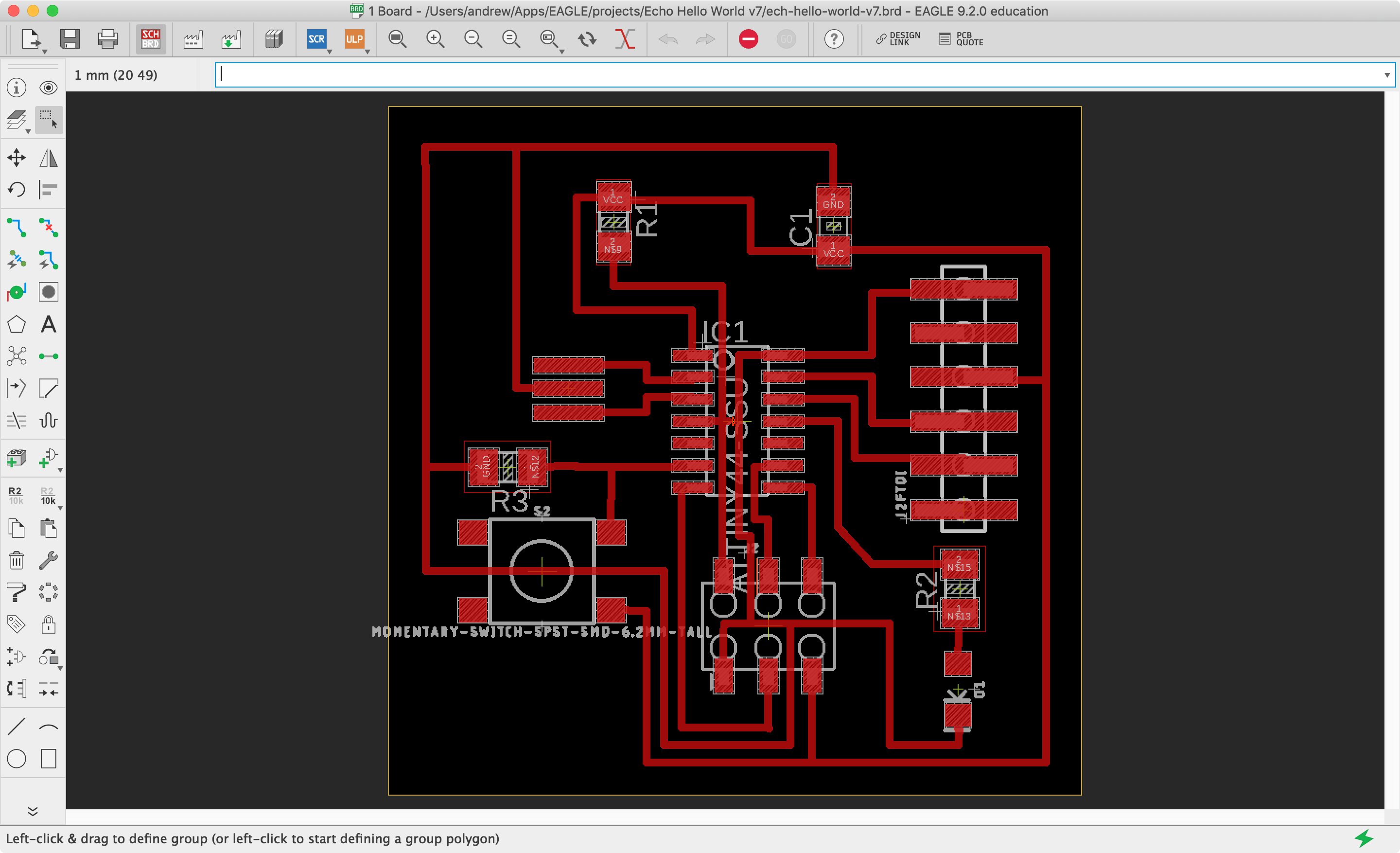
Board layout
Where the components go on the board, and how to route traces (connections between parts) between them.
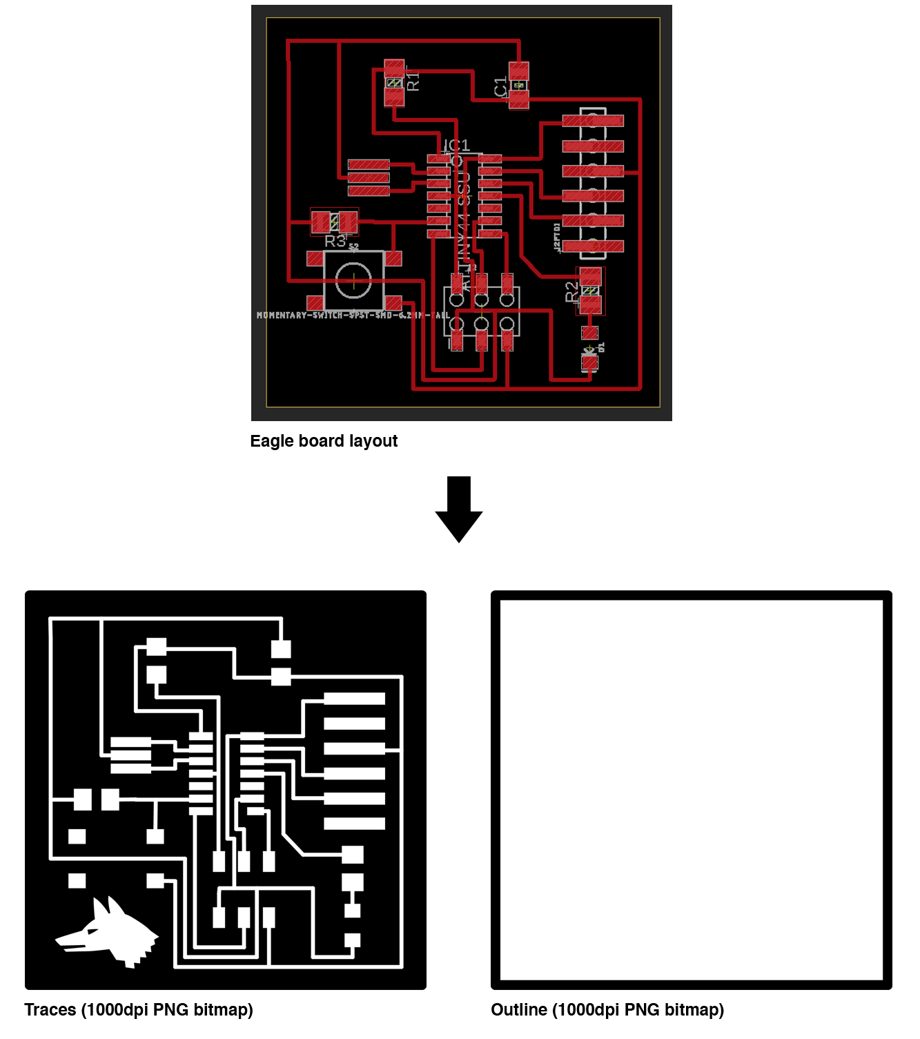
Export and verify
Eagle can generate a layered vector file of traced, pads, labels, and board outline. Use your preferred tools to convert these into 2 PNG files for milling.
See the Detailed guide for more Eagle tips.
Assignment
1) Redraw the Echo Hello World Plus board, starting with this finished circuit:
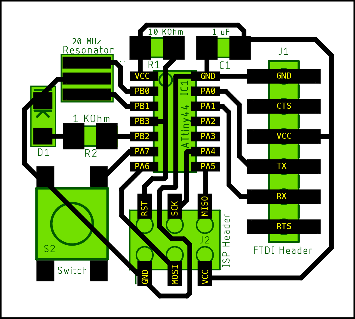
The parts and what they do
| IC1 | Microcontroller | ATtiny44 |
| R1 | Resistor | Holds PB3/Reset pin high |
| C1 | Capacitor | Smooths out noise on VCC/GND line |
| J1 | FTDI header | Serial comms with a computer |
| J2 | ICSP header | Programming with a FabISP |
| D1 | LED | A simple output device you can test with. Brings happiness |
| R2 | Resistor | Limits current to LED |
| Resonator | Resonator | External clock source for chip |
| S2 | Button | A simple input device you can test with |
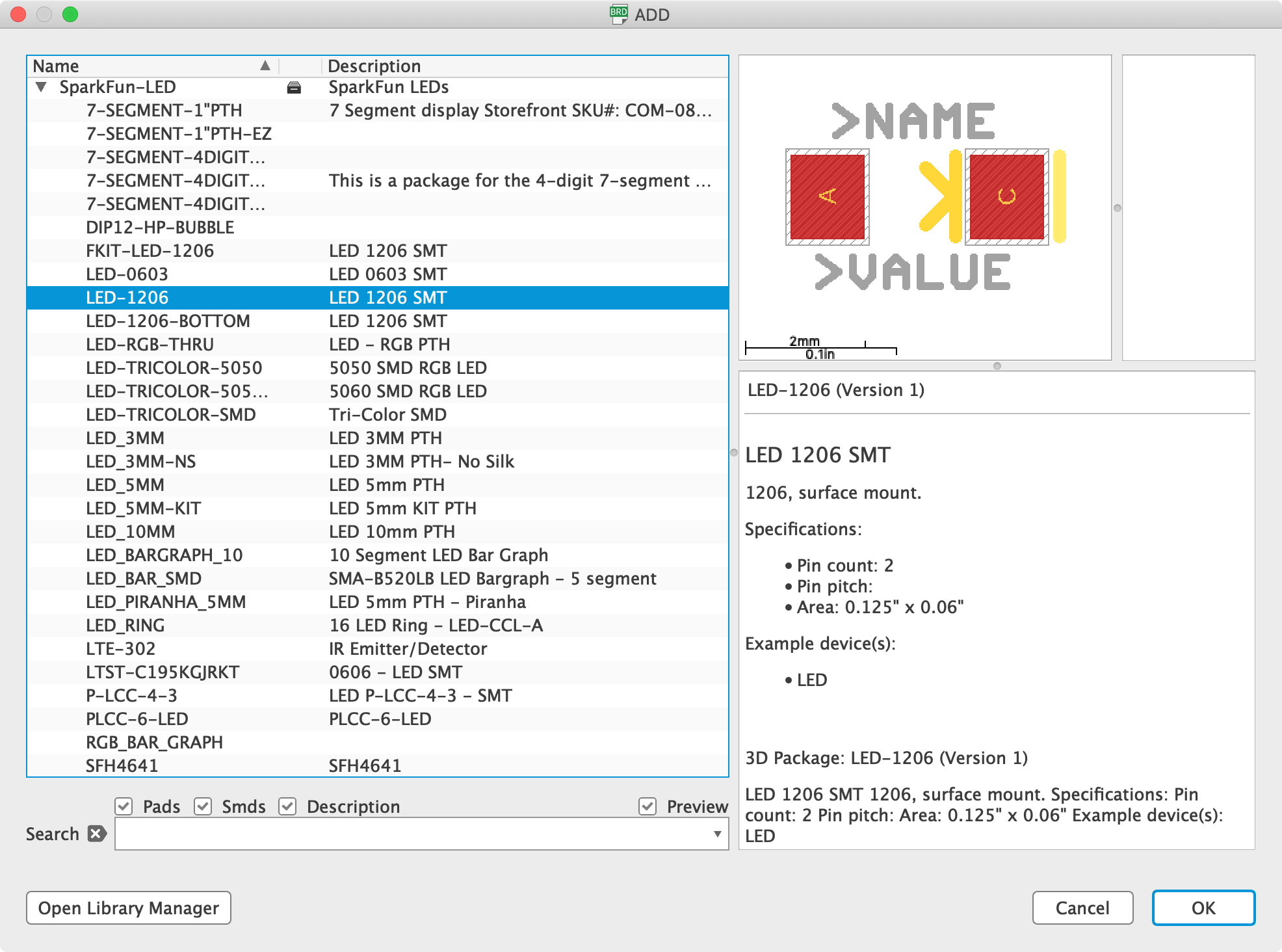
- Use a library in Eagle to get all these parts
- Look at the part bins here to see what we have
- Make sure the parts you select are the right size
- Draw a schematic and board layout
- Export a millable png file of the traces and outline
- How compact can you make it? ( = less waste, less milling time)
2) Make the board
If you have time, mill and stuff the board.
Do this if at all possible!
3) Upload a pre-written program to the board to test that it works
See the board programming guide.
What do I need to do to pass?
Redraw the board in Eagle and generate a PNG file suitable for milling.
Document all your work on your student blog, with photos and videos to show what you did, what went wrong, and how you fixed it. Cite external sources where you have used someone else’s work.
Extra credit
Mill, stuff and test the board by uploading a program. Make the button work reliably (figure out how and why to use a pull-up resistor).
See the board programming guide.
Source material / further reading/watching
- Fab Academy lecture notes: http://academy.cba.mit.edu/classes/electronics_design/index.html
- Lecture from 2018: Fab-20180228D_Lesson06: electronics design
- SparkFun tutorials
- Electronics books:
- Bible: Paul Horowitz, Winfield Hill-The Art of Electronics-Cambridge University Press (2015)
- Good hobbyist starting point: Charles Platt’s Electronics Pages: Books Available
Materials we need this week
- All components for board we make
- Atmel programmer or working FabISPs
- Some pre-made boards for stuffing
- WIP …?
Failsafe for next week
- Commercial Arduinos we can program
- We can continue to mill and stuff boards next week