Guide: Programming an ATtiny board with a FabISP
Uploading a program to a DIY ATtiny microcontroller board through the ICSP header.
Original source material:
Requirements
- A functioning target Echo Hello World Plus board
- Power
- A hardware functioning programmer
- FabISP
- Atmel ICE WIP
- Arduino as ISP WIP
- Software on your computer to upload a program via your programmer
- Arduino IDE installed on your computer, set up to support ATtiny chips
- Or follow Neils Echo Hello World example
- An Arduino (or C) program to run
These instructions mostly assume you’re going to use a FabISP as your programmer, the Arduino IDE (and its bundled tools) as software on the host computer, and an Arduino program to run on your target.
A functioning target Echo Hello World Plus board
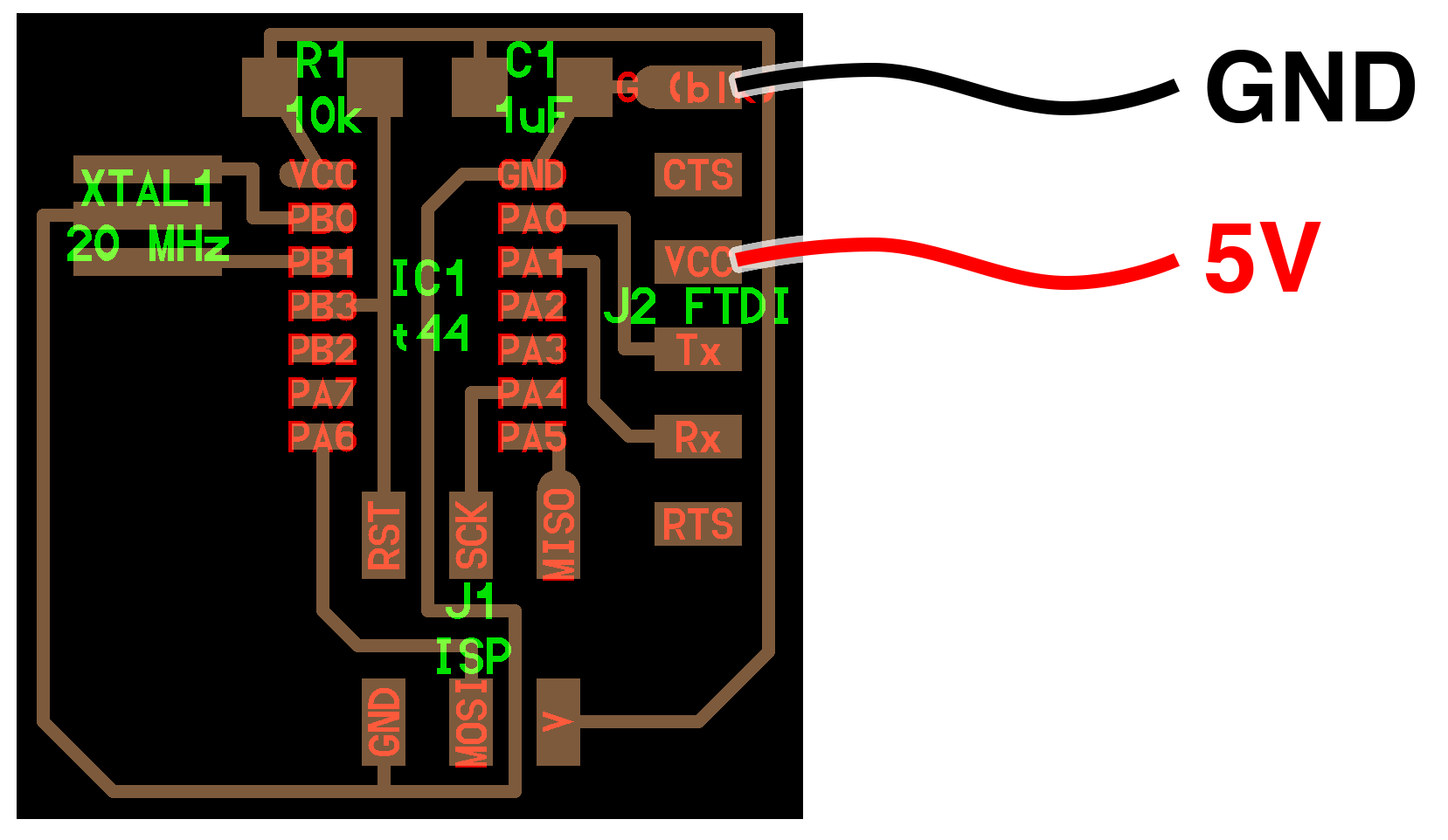
Your target board: The ATtiny44-based Echo Hello World Plus board
Power
Your target board needs 5V DC power to run.
- Connect 5V to the VCC pin (3) of the FTDI header
- Connect Ground to the GND pin (1) of the FTDI header
Where can you get 5V power from?
- Benchtop power supply
- 5V (not 3.3V) FTDI cable connected to USB port on your computer
- An Arduino connected to your computer or a power supply (run jumper wires from the Arduino’s GND and 5V/VCC pins to your board)
Setting up your Arduino IDE
(Assuming you’re using the Arduino IDE to upload programs via your programmer. If not, you can skip ahead to the Echo Hello World C example, which uses lower level C and command line upload tools)
The Arduino software needs to be set up to support the ATtiny chip. Follow the instructions here to install support for the ATtiny to the Arduino IDE: High-Low Tech – Programming an ATtiny w/ Arduino 1.6 (or 1.0)
Menu: Arduino > Preferences
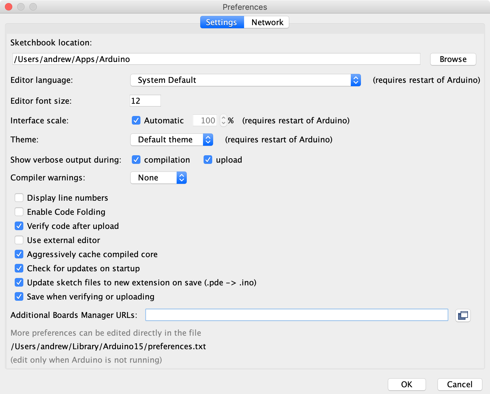
URL to add to the ‘Additional Boards Manager URLs’ field: https://raw.githubusercontent.com/damellis/attiny/ide-1.6.x-boards-manager/package_damellis_attiny_index.json
Menu: Tools > Board (some board name, yours will vary) > Boards Manager…
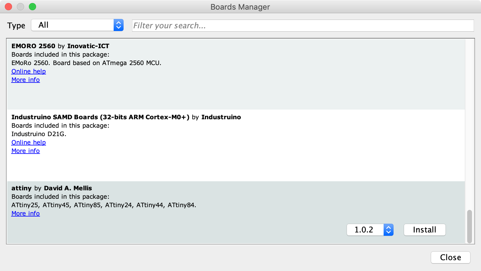
Install ‘attiny’ version 1.0.2. Close the board manager
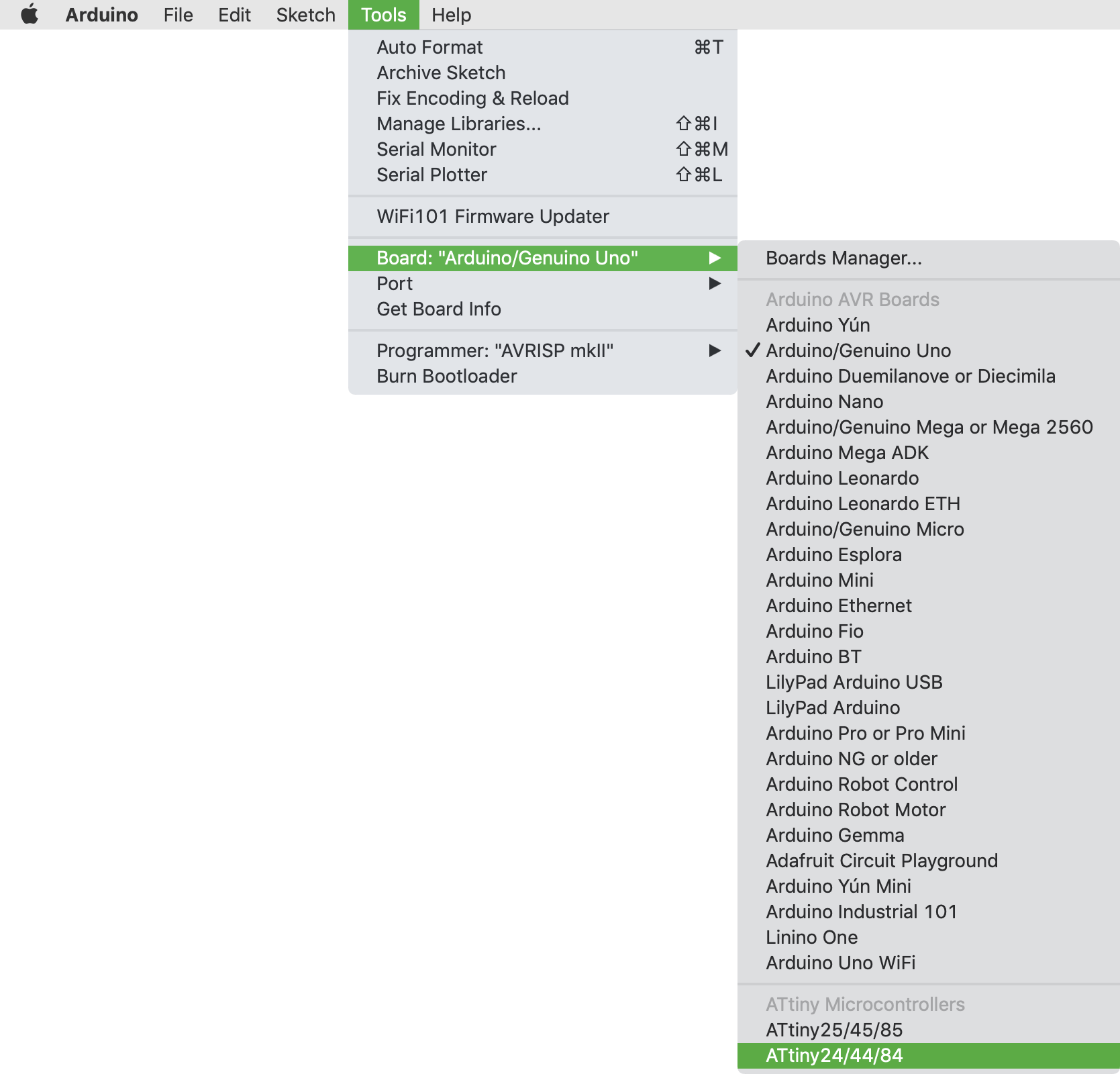
Now choose ATtiny as your target board in the Arduino IDE:
Menu: Tools > Board (…) > ATtiny24/44/84
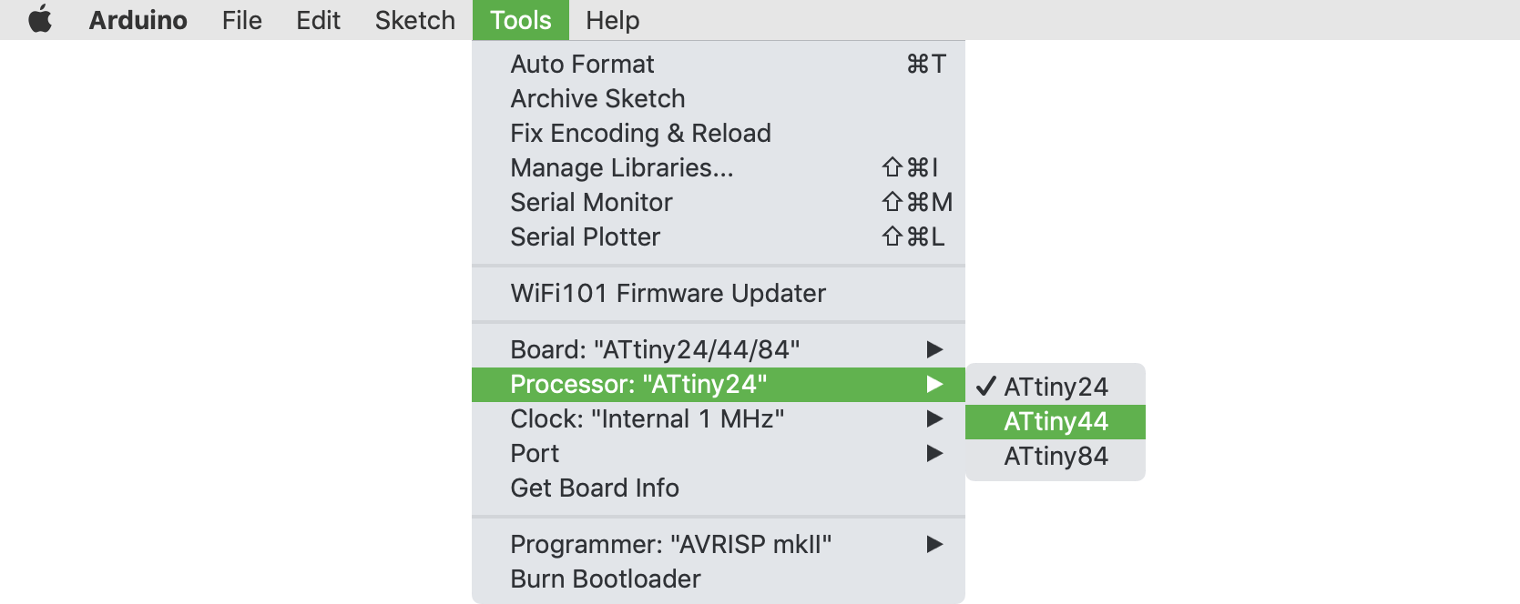
Select ATtiny44 as the processor:
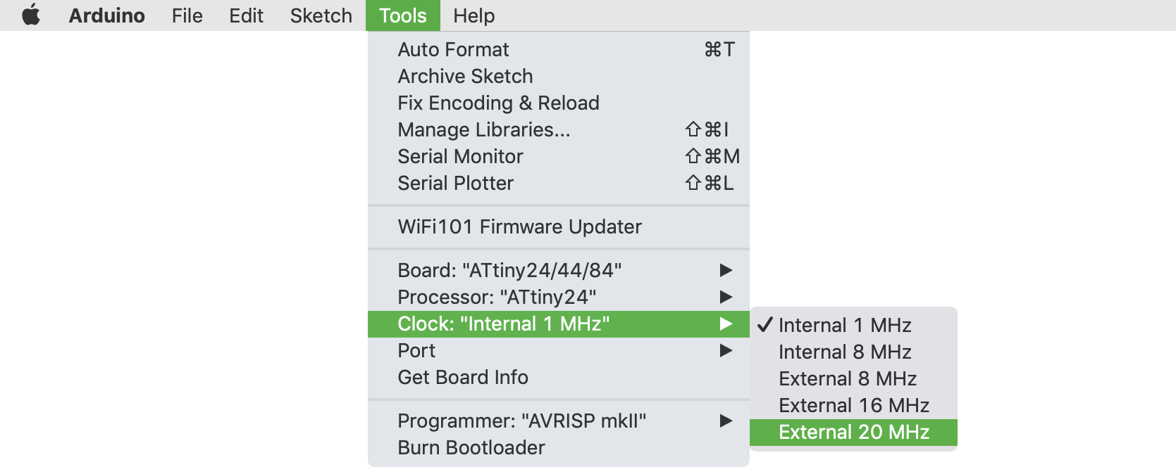
And the External 20 MHz clock:
Programming with the FabISP
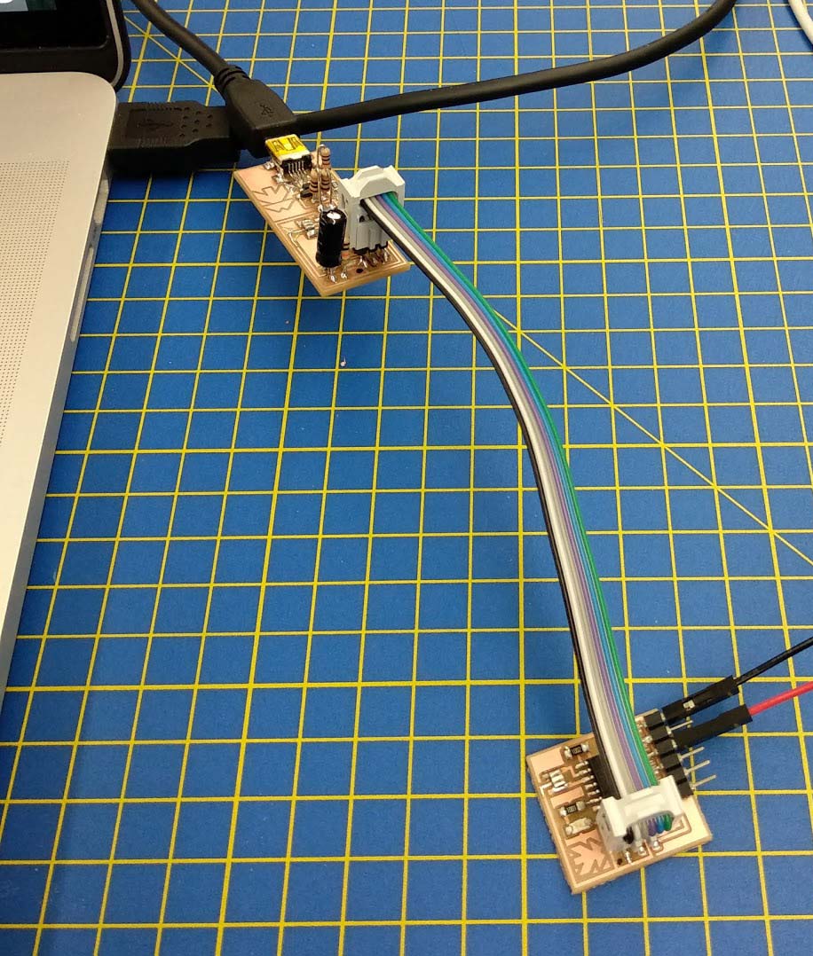
- Connect the FabISP via USB cable to your computer.
- Connect the The FabISP to your target board using a ribbon cable, via the ICSP (=ISP) header, the 6 pin (3 x 2) male header just below the ATtiny chip on your target board.
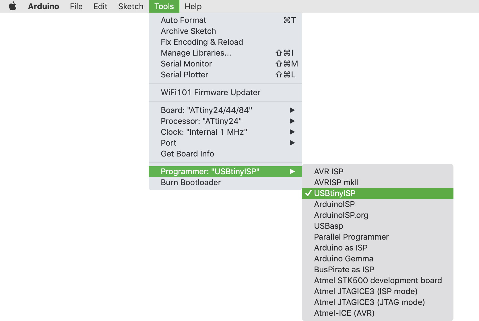
In the Arduino IDE, select USBtinyISP as your programmer:
Menu: Tools > Programmer > USBtinyISP
Then, burn the bootloader to the board
Menu: Tools > Burn Bootloader
If it doesn’t work, check your circuit (visually, and with a multimeter):
- Are the right components in the right places?
- Are all the parts connected as they should be?
- Are the solder connections good?
- Are there shorted pins or damaged traces?
- Is there a power supply connected properly?
- Can you retry with another programmer?
If it does work, upload a program.
Option 1: Blink or Button Sketch via Arduino IDE
If you have modified the board to include a Button and LED, you can try either of these example Arduino Sketches:
Blink: https://www.arduino.cc/en/Tutorial/Blink.
Menu: File > Examples > 01. Basics > Blink
Button: https://www.arduino.cc/en/Tutorial/Button
Menu: File > Examples > 02. Digital > Button
Note: these sketches will need to be edited slightly to work with your board:
Setting the right pin numbers
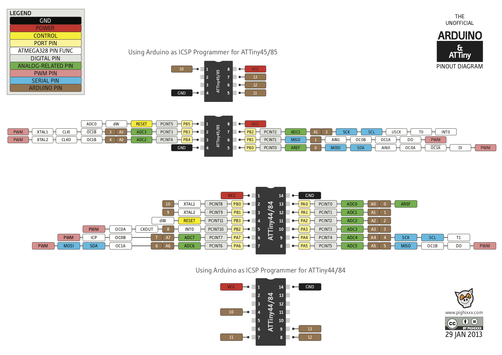
You will need to change the pin numbering in the sketches depending on where you added the button and LED. Consult an ATtiny pinout diagram to see how each pin on the ATtiny chip is referred to in the Arduino IDE.
Enabling the internal pull-up resistor for a button
Buttons should not ‘float’ when unpressed. This will result in unpredictable behaviour. For more on this, see: http://www.thebox.myzen.co.uk/Tutorial/Inputs.html
You can either add a physical resistor to the circuit (as I did) or enable the internal pull-up resistor built into the ATtiny chip. From the datasheet:
Port A (PA7:PA0)
Port A is a 8-bit bi-directional I/O port with internal pull-up resistors (selected for each bit). The Port A output buffers have symmetrical drive characteristics with both high sink and source capability. As inputs, Port A pins that are externally pulled low will source current if the pull-up resistors are activated.
You can do this in the Arduino IDE by using the pinMode() function.
Arduino Reference Arduino - DigitalPins
Option 2: Echo Hello World using command line tools
Arduino packages up a set of tools (e.g. AVRDUDE) and libraries make it easy to program these AVR chips. But the language you’re writing is still just C.
You can also just upload a C program to your board via the FabISP programmer using these tools on the command line.
Neil’s Echo Hello World program is written in C (not using Arduino libraries) so needs to be uploaded in this way: http://academy.cba.mit.edu/classes/embedded_programming/hello.ftdi.44.program.png
Programming via an Arduino board
If your FabISP programmer isn’t working, you can also use a commercial Arduino board as a programmer.
WIP: untested
Docs here: High-Low Tech – Arduino board as ATtiny programmer
Also:
Programming ATtiny ICs with Arduino Uno and the Arduino IDE 1.6.4 or above |
Note that these docs assume you’re putting the ATtiny chip on a breadboard. In our case, we would connect to the MOSI, MISO, RESET, SCK pins on the 3x2 ICSP header on the target board.
Programming via an Atmel ICE programmer
WIP: untested