Guide: Making a mould tool using a CNC machine
Making a mould tool using a CNC machine.
How to make an open mould tool on the 1610 GRBL milling machine
This guide takes you through the process of creating a simple open mould tool.


The idea here is that you don’t actually have to design the tool. Instead, by cleverly positioning your part inside the stock material, you can machine it in a way that when you cast silicone resin into it, it will create a female mould tool that is ready to make your solid parts. In this guide I have used the example of making a small chocolate tile. I’ve designed the tile part in Fusion, then machined it out of a piece of stock (50 x 50 x 3 mm) which left a cavity that becomes my actual mould tool. I then cast food safe silicone resin into the mould tool and left it to set for a day or two. Once set, I then cast in my chocolate, set it in the fridge, and gave it to my daughter who gobbled it up! Some key definitions:
- CAM: computer-aided manufacture
- stock: the material you start with that will be cut on the machine
- mould tool: a machined part, into which your part can be cast or moulded
- toolpath: the path taken by the cutting tool to cut your stock
- operation: a particular cutting process. You will utilise multiple operations to cut your stock
- g-code: the common name for the most widely used numerical control (NC) programming language. This is the code that controls the CNC milling machine
1. Starting point: a component in Fusion 360
 It is best to make the top of your part parallel with the ‘FRONT’ plane (just like in this image). This will make things easier when it comes to setting the co-ordinate system in the CAM.
2. Generate a tool path (CAD to CAM)
CAM software: Fusion 360 again! move between ‘model’ and ‘manufacture’ modes in Fusion 360. Tip: hover your mouse over any input box and Fusion gives a very good description of what is required. I recommend using this frequently. 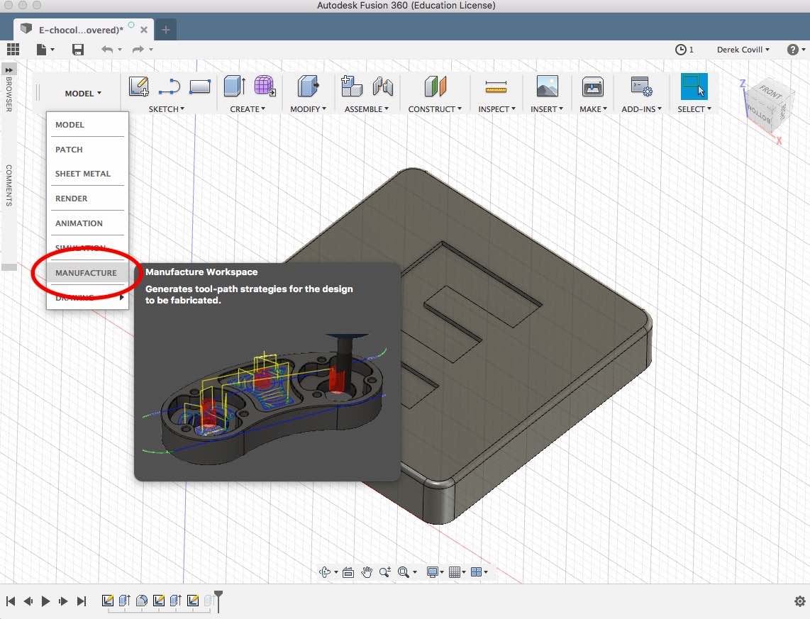
CAM setup
Click on setup (next to ‘manufacture’). For this guide, we want the origin to be on the top of the stock in the centre, with the ‘z’ direction vertical. This should happen if the ‘front’ view is aligned with the top if your part.
 For the stock setup, we want to ‘add stock to sides and top-bottom’. Note that this isn’t always the case, but works well for this guide. Our stock is 50 x 50 x 10 mm (x,y,z), and the final part will be 30 x 30 x 5 mm, so we want to add 10 mm to the sides, 3 mm to the top and 2 mm to the bottom. Since we’ll be using a 3 mm cutter, that means when it comes to casting into the mould cavity there will be a 3 mm moat all round the sides and a 3 mm gap on the top. Essentially our mould tool will have walls 3 mm thick all round (sides and bottom).

In the post process tab give your output file a meaningful name in the ‘Program Name/Number’ box, e.g. ‘CNC-tile-30x30x5-derekcovill-pink-foam’. When it comes to saving the file later, this is the file name it will use, e.g. ‘CNC-tile-30x30x5-derekcovill-pink-foam.nc’. Leave all the other boxes as they are and click ‘OK’.
CAM operations
You then need to create a series of operations to cut out your part. These can be found by right clicking on the ‘setup’ area and deleting ‘new operation’, or by clicking the 2D or 3D icons as shown below.  Note that there are lots of types of operations. For the simple tile designed above we used 3 operations (all 2D operations): face, 2D pocket, and 2D contour. It’s worth reading up on the various 2D milling operations (common ones are: 2D pocket, 2D contour), and 3D milling operations (common ones are: adaptive clearing, morphed spiral,) here’s a link to a the autodesk reference. And also the and note the difference between roughing and finishing processes. We then move through the tabs from left to right to define the input requirements of each operation. Typically these will be something like: _Tool > Geometry > Heights > Passes > Linking

Operations: tool
For all processes select the same tool, that should be: Samples > Metric - High Carbon Steel > φ3mm - flat (3mm Flat Endmill).  Don’t worry about the Feed and Speed settings at this stage, but it’s worth noting them as you go.
Operations: Geometry
You then need to select the geometry that defines the type of cutting operation required. In the case shown below, the top edge defines both the area and the depth required for this 2D ‘face’ milling operation. 
Operations: heights
We then define the relevant heights for the following (I suggest working upwards from the bottom): Bottom Height > Top Height > Feed Height > Retract Height > Clearance Height Note: for this guide we only really need 3 different heights:
- Bottom Height (where we cut down to) - shown in purple below
- Top Height (where start cutting) - shown in blue below
- Tool moving heights (ie Feed/Retract/Clearance are the same) - shown in green below
When setting heights it is very important to really get it right - any mistakes could mean the machine crashes into your stock which can cause real damage… or worse, it crashes into itself and it will probably ruin the machine. 


Operations: passes
We then define how the machine creates the cutting passes. In particular we want the following settings:
- Stock Offset: 0.5 mm
- Stepover: 1.5 mm
- Multiple depths > Maximum step-down: 1 mm
These are important settings to get right - otherwise the machine will need to work too hard to cut the material and could damage the machine. 
Operations: linking
Typically these settings can be left as they are, but again note them just to understand what they are. Then click OK to complete the operation and the tool path should be shown on the screen. Once you’ve completed the operation definition, you can go back and edit it (right click on the operation in the list of operations browser on the left). You can also look at the machining time for all the operations. In the case of this tile, it will take 7 mins 22 seconds.
3. Simulate/generate tool path and post-processing
Actions: Simulate
It is also a very good idea to simulate the tool path, noting:
- the speed of movement when cutting: does it seem unnvervingly fast or overly slow for the material you’re cutting?
- the speed of movement when not cutting: does it seem unnervingly fast or overly slow?
- plunging speed: when the tool moves down to start cutting, does it seem too fast or slow?
- the number of paths per cutting layer: does it cut several passes per layer unnecessarily?
- the size of the step-downs: does it cut too many layers (too shallow), or few (too deep)?
- start and finish location of the tool: does it start from and finish at the origin (xyz=0: in this case in the middle at the top of the stock?)
 Once you’ve done all the operations required to machine your part, you can then simulate the entire machining process including all operations. I recommend showing the stock and toolpath, and hiding the tool. So cool!
 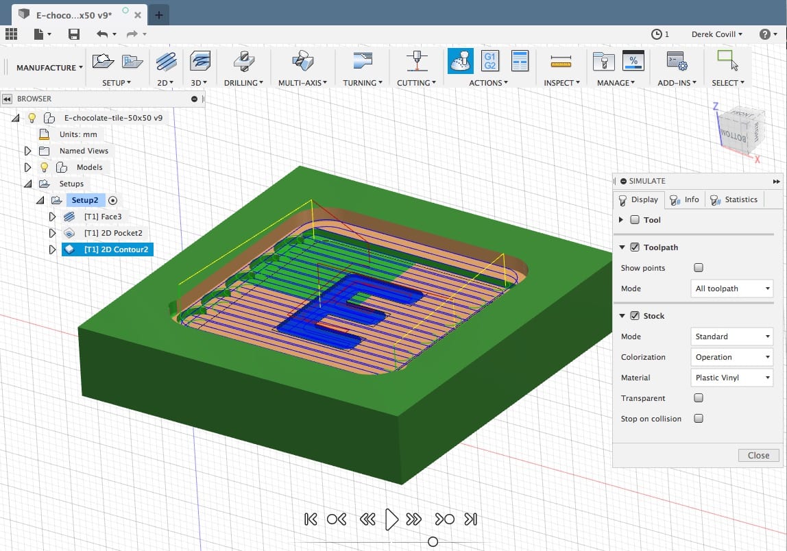 and here’s an animation of the tool path:
Actions: Generate
We then need to generate the tool path for all the operations. Make sure you do this before you post-process to make sure the final programme reflects any changes you’ve made to the operations or setup.
Actions: Post process
We then need to define the post-processor. This effectively defines the format of the machining code so that it conforms to requirements of the particular machine we’re using. In this case, the post-processor is ‘Grbl’. Click OK to then save your g-code file. Note that the Grbl file format for the g-code is a .nc file.  Once you’ve saved your .nc file, make sure you save your fusion 360 component and here’s what the g-code should look like in your .nc file:
% (E-faster-60mm-plungev2) (T1 D=3 CR=0 - ZMIN=-8 - flat end mill) G90 G94 G17 G21 G28 G91 Z0 G90
(Face3) M9 T1 M6 S5820 M3 G54 M8 G0 X16.832 Y-13.743 Z3 G1 Z-0.7 F349.2 G18 G3 X16.532 Z-1 I-0.3 G1 X15 X-15 G17 G2 Y-11.014 J1.364
etc….
4. Setting up the milling machine
We then move from the PC to the actual 1610 CNC milling machine. 
Safety
Some notes on safety:
- this is an exposed machine and can cause serious harm - never touch the machine while it is running
- everyone must be trained by a member of staff in order to use the machine (a record of who has been trained can be seen here)
- if in doubt: ask. A member of staff can always do the cutting for you
- never use the machine alone
- never leave the machine running unattended
- safety guard must be put on the machine before it is started up
Prepare the bed and material
- Sacrifical material
- Must be flat and clean
- With a marker, draw two lines from corner to corner on the top of your workpiece to get the center
Place your stock on bed
- Apply double-sided tape to the bottom of your stock
- Place your part approximately in the middle of the bed (our stock for this guide is small: there’s plenty of space so no need to be perfect here)
- Don’t tape your stock down yet!
Select and install the cutting tool
- Select your cutting tool (flat end mill, 3mm diameter)
- Place it in the collet and nip it up tight with the allen key (attached to z-axis gantry)
- Check that the bit is centred by rotating the collet with your hand and looking at the end of the bit to see if it wobbles or not
- check that the height is suitable to cut your part (where the end of the cutting tool is not to high, not too low)
- Plug the 1610 CNC mill into the mains (plug labelled 1610 CNC)
5. Send your .nc file to the 1610 machine
On the PC next to the machine (or on any windows laptop), load the GRBLcontrol programme (on the desktop). Open your .nc file in GRBLcontrol
Set the xy zero and z zero
- Move x and y axes until it’s above the centre mark
- Lower tool to surface (z direction) until it touches the centre mark then set z0, and set xy0. Always spin the tool when setting z so you know when it’s just touching
- Remove your stock from the bed
- Make sure everything is out of the way (e.g. cables, swarf)


Mill fresh air
- When you press ‘Send’, the machine will start milling
- Stand by and be ready to pause or abort in the software in case something goes wrong
- Keep an eye on what the machine is doing - is it doing what is expected? if not then abort and revisit the operations in Fusion 360.
Mill the stock
- place your stock on the board, taping it down onto the sacrificial layer
- again position the tool on the centre of the top of the workpiece and set z0 and xy0
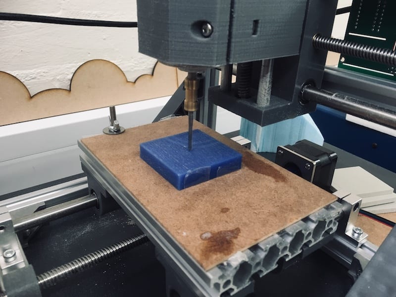
- make sure your spindle speed is set at 1000 rpm
- if you’re using low (blue or yellow) or medium (grey) density foam, then there’s no need to over ride the speed of the machine (keep it at 100%)
- if you’re using high density foam (pink), then you’ll need to set the override to 75% before running the machin
- if you’re using blue wax, then you’ll need to set the override to 30% before running the machine
- then hit Send and the machine will start running again
- remember not to leave the machine running unattended - ever


6. Clean up and check your part
- Move the gantry with the cutting tool out of the way of your part - this will stop you scraping the sharp tool as you remove your part
- Using the ‘ghostbusters’ style hoover, hoover up all the swarf from your part
- Remove your part from the sacrificial board - you may need a lever
- Hoover around the machine and wipe it down with a cloth to make sure it is completely free from debris and dust
- Inspect the part and hoover it again now that it’s in your hand you can get any last specs of dust
- Your stock has now been turned into a new mould tool!
7. Cast into your new mould tool
Using a food safe silicone (if you want to eat the produce!) mix up the two-part concoction and pour/smear it into the mould. Some notes on this:
- it is very gloopy and it is very easy to make a real mess - take your time and keep the mess contained
- have lots of disposable workshop roll to hand, ideally cut into sections before starting
- wear PPE (gloves, glasses, lab coat)
- work only in a well ventilated area (it stinks)
- create a clear (or even better covered) work surface to work on
- get some disposable spatulas and cups to work with - bear in mind it is very viscous stuff so you’ll need something not too flimsy
 Mix up just enough material to fill up the cavity in your mould tool making sure you get the right ratio of silicone to hardner (use a cup with measuring lines on it or use a set of scales).
  Once the silicone has been mixed and poured, let it set for at least 24 hours. Note that wax mould tools will allow the silicone to set quite quickly (approx. 24 hours), while foam mould tools might take longer (e.g. 48 hours). You can use an oven to accelerate the process. Remove the silicone part from the machined mould tool. Your silicone part is now a new mould tool that you can cast chocolate into!