Guide: Programming a new FabISP Programmer
How do you program a new FabISP Programmer board?
This process can be confusing and complicated for non-specialists, so I’m compiling some notes here.
Original source material:
- http://archive.fabacademy.org/archives/2016/doc/programming_FabISP.html
- Arduino as an ISP
- ATtiny44A Fuses
- http://fab.academany.org/2018/labs/fablabbrighton/students/andrew-sleigh/assignments/2018/02/15/wk5-mill-pcb.html
- Building the FabTinyISP
This guide focuses on Mac, for other platforms see:
- http://archive.fabacademy.org/archives/2016/doc/programming_FabISP.html
- Building the FabTinyISP
Understanding terminology
From Building the FabTinyISP:
One possible point of confusion in this document is that the device you’re building will become an AVR programmer, but you also need a working AVR programmer in the process of building it. Your board refers to the new programmer that you are building. Programmer refers to the working programmer that you’ll use to initialize yours. At the end of this document, your board becomes a programmer.
I’ll follow this convention.
Using the command line
You’ll be running commands in the Terminal (or Windows/Linux equivalent). Some introductions:
- http://fab.cba.mit.edu/classes/863.16/doc/tutorials/bash/bash.html
- https://blog.teamtreehouse.com/introduction-to-the-mac-os-x-command-line
Workflow
- Download software tools
- Download the firmware for the programmer
- Customise the Makefile
- Plug your programmer into your computer, and your target board into your programmer
- Power the target FabISP Board
- Compile and install the firmware
- Break the line to VCC on the ISP header (and to RST on the 44 boards)
- Test that your programmer works
The instructions differ slightly depending on which programmer you’re making.
- Brian’s, based on the ATtiny45 (I’ll call this FabTinyISP/45)
- Ali’s, based on the ATtiny44 (I’ll call this FabISP/44)
Download software tools
Crosspack
Download and install: https://www.obdev.at/products/crosspack/index.html
Restart Terminal.app after installation.
(Crosspack has no GUI - it runs on the command line, in Terminal)
Manual: <file:///usr/local/CrossPack-AVR-20131216/manual/gettingstarted.html>
Make
Install Make:
- You can either do this from Xcode (available from the Mac App Store).
- Or just install the Xcode Command Line Tools from Apple: https://developer.apple.com/downloads/index.action
For more on Make and Makefiles, see below
Download the firmware for the programmer
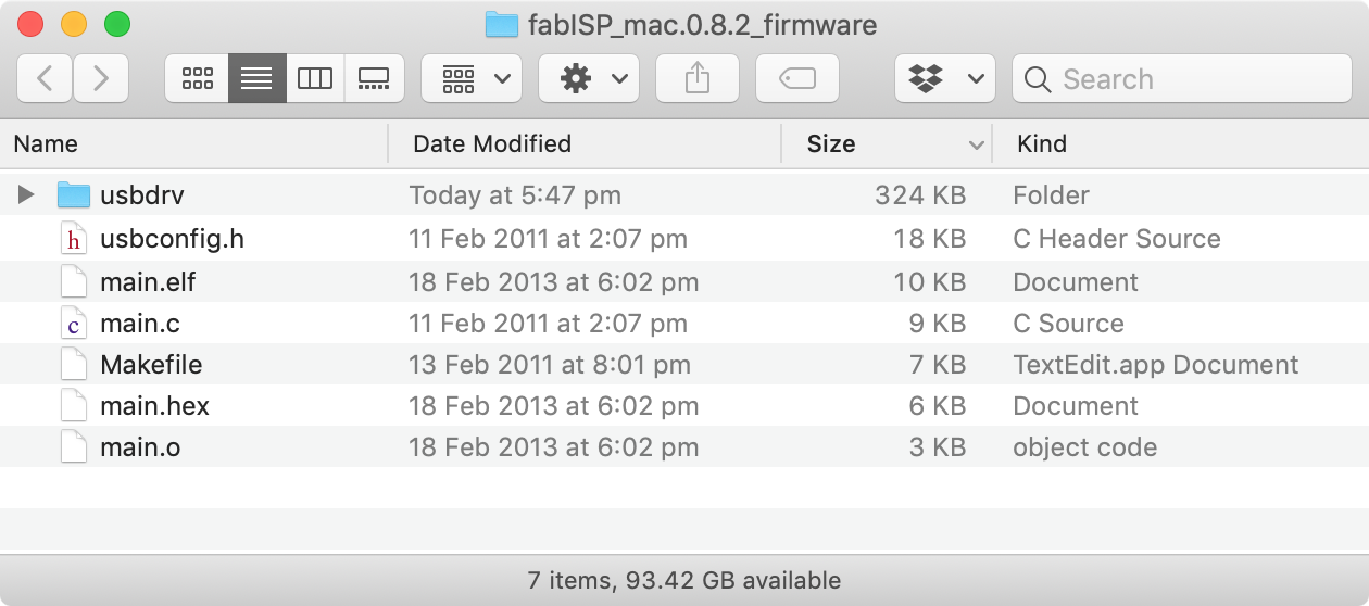
FabISP/44
Download for Mac: http://www.as220.org/fabacademy/downloads/fabISP_mac.0.8.2_firmware.zip
Unzip the downloaded file.
Open the folder:
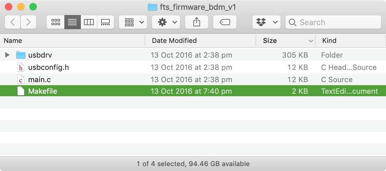
FabTinyISP/45
http://fab.cba.mit.edu/classes/863.16/doc/projects/ftsmin/fts_firmware_bdm_v1.zip.
Unzip the downloaded file.
Open the folder:
Customise the Makefile
Whichever firmware you’re using, open the Makefile in a text editor (e.g. TextEdit), not a word processor. Note, you can comment out a line (so it doesn’t execute) by adding a hash mark to the beginning)
Target chip
Different FabISP designs use different chips, e.g:
- FabTinyISP: ATtiny45
- FabISP: ATtiny44
Make sure the line specifies the right chip.
FabTinyISP/45 Makefile: this is the relevant line:
MCU = attiny45
FabISP/44 Makefile: this is the relevant line:
DEVICE = attiny44
Clock speed
Your chip can run at different speeds. Some FabISPs use an external crystal to set the clock speed, though the FabTinyISP does not. Specify the correct speed in Hz here. (20 MHz = 20,000,000 Hz)
FabTinyISP/45 Makefile: this is the relevant line:
F_CPU = 16500000UL
FabISP/44 Makefile: this is the relevant line:
F_CPU = 20000000 # edit this line for crystal speed, in Hz
Which programmer you’re using to program your board (the target programmer)
I’m going to assume you’re using another FabISP to program your board. These behave like USBTiny ISPs, and are referred to as usbtiny in the makefile.
FabTinyISP/45 Makefile: this is the relevant line:
PROGRAMMER ?= usbtiny
FabISP/44 Makefile: this is the relevant line:
AVRDUDE = avrdude -c usbtiny -p $(DEVICE) # edit this line for your programmer
#AVRDUDE = avrdude -c avrisp2 -P usb -p $(DEVICE) # edit this line for your programmer
A # denotes a comment, so in this case, only the first line executes.
There are other options if you’re using a different programmer to program your target board. From Building the FabTinyISP:
Small translucent blue programmer : avrisp2
Large translucent blue programmer : jtag2isp
White box with blue stripe : atmelice_isp
Any fabbed board with an ATtiny on it: usbtiny
Plug your programmer into your computer, and your target board into your programmer
Plug your programmer into your computer
FabISP/44: If your programmer has a USB port, use the correct USB cable.
FabTinyISP/45: If your programmer has built-in USB pins, it is safer to connect it to your computer with a USB extension lead:
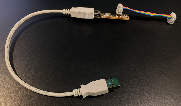 Image: Building the FabTinyISP
A note on USB 3:
There have been reports of problems with certain USB-3 ports due to the stricter timing USB-3 requires, from what I’ve understood all FabISPs seem to be suffering from this. The workaround is to try another USB port or even an USB-2 (or lower) hub. As I don’t have any USB-3 ports (yet), I cannot really test this myself.
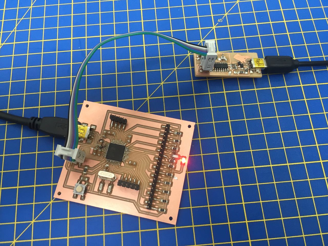
Plug your target board into your programmer
You’ll use the 6-wire ribbon cable.
Ensure each pin on the programmer is connected to the same pin on the target. Depending on how your cable is made, this might look different to other setups.
Power the target FabISP Board
Your target board also needs power.
Plug it into a computer via USB. This USB connection is just providing power; your target board is not communicating with the computer through this port. You could also plug it into a 5V USB power supply.
Compile and install the firmware
Each firmware Makefile works slightly differently. See the specific instructions for more details on each one. In summary:
FabTinyISP/45, firmware: “fts_firmware_bdm_v1”
Full instructions: Building the FabTinyISP
- Run
make flash(erases and programs the target) - Run
make fuses(set up all of the fuses except the one that disables the reset pin) - Test the USB functionality (check the new programmer appears as a device in Apple System Profiler)
- Run
make rstdisbl(blow the rest fuse) - Disconnect VCC from the VPROG pin on the ISP header by removing the bridge on the solder jumper
FabISP/44, firmware: “fabISP_mac.0.8.2_firmware”
Full instructions: FabISP: Programming
- Run
make clean(clean up old files) - Run
make hex(compile the firmware) - Run
make fuse(set the fuses) - Run
make program(programs the target) - Test the USB functionality (check the new programmer appears as a device in Apple System Profiler)
- Remove the 0 Ohm resistor and solder bridge
It’s likely that you will run into problems in this process. The docs for each of these boards give some guidance on what to try. Document your troubleshooting steps as you go.
Break the line to VCC on the ISP header (and to RST on the 44 boards)
So far, your FabISP board has been a target. The final step for it to be programmer is to disable the ability for it to be reprogrammed itself. Setting the fuses is part of this, but you also need to make some changes to the board:
- FabTinyISP/45: Break the solder jumper connected to VCC pin on the ICSP header
- FabISP/44: Break the solder jumper connected to Pin 4/PB3 on the ATtiny44, and remove the 0 Ohm resistor connected to the VCC pin on the ICSP header
Test that your programmer works
Your target board should now itself be a programmer!
Unplug it from the original programmer.
Try using it to program another board via the ICSP header. Plug your new programmer into your computer via USB Connect it to the target board with the 6-wire ribbon cable, making sure to orient it correctly Try uploading a sample sketch from the Arduino IDE, making sure to use the “Upload Using Programmer” option.
More technical background: AVRDUDE, makefiles and fuses
The guides that this material is derived from skip over the technical detail, which is fine when everything work. But generally, especially for beginners, it doesn’t work first time. So it’s useful to understand what’s going on, so you can fix problems.
AVRDUDE
Yep, stupid-sounding name – it (barely) stands for AVR Downloader and UploaDEr. (AVR apparently doesn’t stand for anything, it’s just the name for the family of chips that we often use (ATtiny, ATmega, etc.).)
It’s a command line program for uploading programs to AVR chips.
AVRDUDE comes packages as part of Crosspack on the Mac (It’s also built into the Arduino IDE, and you can see AVRDUDE console messages in Arduino, when you upload a sketch to your board.)
We’re using it here to upload the programmer software to the target through the existing programmer, and then set some fuses on the target chip to configure it for our particular setup (e.g. whether or not you used an external clock source).
You probably won’t actually write AVRDUDE commands, because they’re set up in a Makefile. The Makefile has instructions to set the fuses on the chip to specific values. See example below.
Some more info:
What are ‘Make’ and ‘Makefiles’?
From the Make command line manual:
The purpose of the make utility is to determine automatically which
pieces of a large program need to be recompiled, and issue the commands
to recompile them.
…
To prepare to use make, you must write a file called the makefile that
describes the relationships among files in your program, and the states
the commands for updating each file. In a program, typically the exe-
cutable file is updated from object files, which are in turn made by
compiling source files.Once a suitable makefile exists, each time you change some source
files, this simple shell command:make
suffices to perform all necessary recompilations. The make program
uses the makefile data base and the last-modification times of the
files to decide which of the files need to be updated. For each of
those files, it issues the commands recorded in the data base.
In software development , Make is a build automation tool that automatically builds executable programs and libraries from source code by reading files called Makefiles which specify how to derive the target program.
This is a good tutorial: What is a Makefile and how does it work?.
We’ll get into one example of how a Makefile is constructed, and what it actually does, when we look at fuses, below
Fuses
From AVR Tutorial - Fuses:
there are also 3 bytes of permanent (by permanent I mean that they stick around after power goes out, but that you can change them as many times as you’d like) storage called the fuses. The fuses determine how the chip will act, whether it has a bootloader, what speed and voltage it likes to run at, etc. Note that despite being called ‘fuses’ they are re-settable and don’t have anything to do with protection from overpowering (like the fuses in a home).
So fuses are just little banks of software switches you can set inside the ATtiny chip to set some very basic preferences about how you want it to run. For all this simplicity, the way they’re set, using strange values like ‘0x7F’, is not particularly accessible, so it’s worth figuring out what these terms mean.
Representing fuse values: bytes, bits, binary, and hexadecimal
1 byte = 8 bits.
A bit can hold 1 piece of data, either a 1 or a 0.
A byte can hold a string of 8 bits, like 1 0 0 0 1 0 1 1, or 0 1 1 0 0 1 0 0
There are 256 possible permutations of bits in each byte (numbers 0 – 255 in decimal).
A range of numbers from 0 to 255 can also be represented with a 2 digit hexadecimal number, for example:
| Binary (bits) | Decimal | Hexadecimal |
|---|---|---|
01111111 |
127 | 7F |
01010101 |
85 | 55 |
11111110 |
254 | FE |
11111100 |
252 | FC |
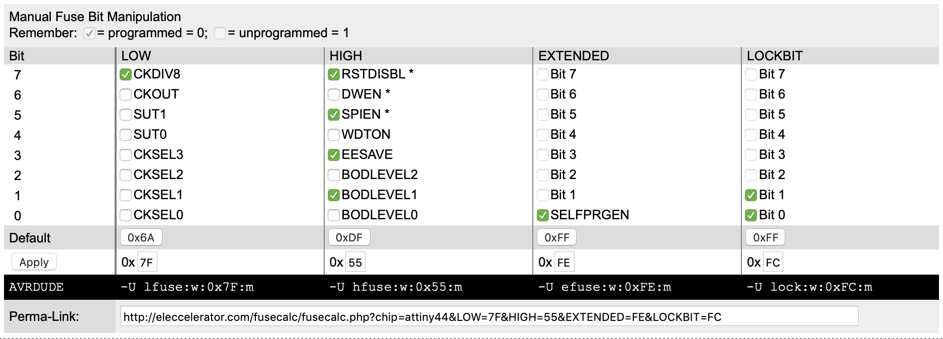
You can see these same values in the screenshot of an online fuse calculator below. Each of these 4 columns represents one of the fuses (or banks of switches in our metaphor)
Note, in these examples:
- Bit IDs count down from 7 to 0, left to right
- In this representation, the least significant bit is last (ie a the end of the list, or bit number 0 in the fuse table
This calculator lets you set 4 fuses (LOW, HIGH, EXTENDED and LOCKBIT). Most only set the first three, and even the EXTENDED fuse has only one bit that can be set, “SELFPRGEN” or “Self Programming enable”.
To set the fuses in your chip, you program them with AVRDUDE. The screenshot shows the instructions needed for these settings:
- -U lfuse:w:0x7F:m
- -U hfuse:w:0x55:m
- -U efuse:w:0xFE:m
- -U lock:w:0xFC:m
Bringing it all together: Setting a fuse with AVRDUDE, configured in a Makefile
You might notice that the HIGH fuse has a bit called RSTDISBL. The ATtiny44 Datasheet details this on pin PB3, which has an alternative function:
Port B (PB3:PB0)
Port B is a 4-bit bi-directional I/O port with internal pull-up resistors (selected for each bit). The Port B output buffers have symmetrical drive characteristics with both high sink and source capability except PB3 which has the RESET capability. To use pin PB3 as an I/O pin, instead of RESET pin, program (‘0’) RSTDISBL fuse. As inputs, Port B pins that are externally pulled low will source current if the pull-up resistors are activated. The Port B pins are tri-stated when a reset condition becomes active, even if the clock is not running.
When you set the RSTDISBL bit of the HIGH fuse to 0 (programmed), you are telling the ATtiny that you want to use Pin 4/PB3 as a an I/O pin, and therefore disabling its ability to be used as a reset pin. Without the use of the reset function on this pin, the chip itself can’t be reset, so the board can no longer be programmed (unless you change the fuse again). By this stage in the process, you’ve already loaded a program onto the chip (the program that allows it to program other boards), so unlike most other boards you might make, you don’t want to allow this board to be reprogrammed to do something else. It will only ever be an ISP programmer.
Let’s look at an example of how fuses are set in a Makefile in more detail.
In the FabTinyISP/45 (fts_firmware_bdm_v1) Makefile, one of the ‘targets’ is called rstdisbl:
rstdisbl:
	$(AVRDUDE) -p $(MCU) -c $(PROGRAMMER) -P usb \
		-U lfuse:w:$(LFUSE):m -U hfuse:w:$(HFUSE_RSTDISBL):m \
		-U efuse:w:$(EFUSE):m
A target is like a function in a programming language.
Below the target, indented by tabs, is the ‘recipe’. The recipe contains variables, denoted like this: $(VARIABLE_NAME). The value for these variables is set further up in the file. So we can see that $(HFUSE_RSTDISBL) will be replaced by 0x5D according to this assignment:
# Fuse bit settings with reset pin disabled
HFUSE_RSTDISBL=0x5D
‘0x’ simply means that the number following is in hexadecimal. So what does the hex number 5D signify?
Going back to our fuse calculator, if we specify the HIGH fuse to be set to a hexadecimal value of 5D, it sets the bits as follows:
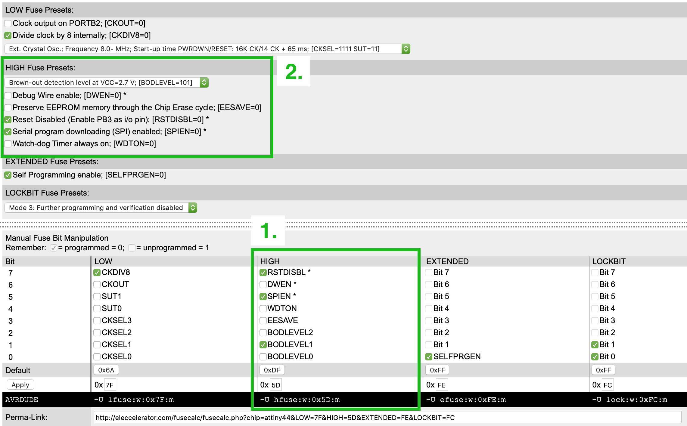
Enter the hex value in the HIGH column of the ‘Manual Fuse Bit Manipulation’ section (box labelled 1). This checks the first bit (number 7), i.e. sets it to 0 (yes, the way everything is the opposite of what you think it should be is confusing!).
This sets the presets in the ‘HIGH Fuse Presets’ section (box labelled 2), including checking the ‘Reset Disabled (Enable PB3 as i/o pin); [RSTDISBL=0]’ box.
Disabling reset on the chip means that it can no longer be programmed (i.e. it is safely frozen in state with the program we’ve just loaded on.)
For the sake of completeness, lets expand out all those variables, which are all set further up the file:
# Set up which MCU you're using, and what programmer, and the clock speed
# here.
MCU = attiny45
PROGRAMMER ?= usbtiny
F_CPU = 16500000UL

# Fuse bit settings
EFUSE=0xFF
HFUSE=0xDD
LFUSE=0xE1

# Fuse bit settings with reset pin disabled
HFUSE_RSTDISBL=0x5D

# Edit these if you want to use different compilers
CC = avr-gcc
OBJCOPY = avr-objcopy
SIZE = avr-size
AVRDUDE = avrdude
Using these values, our rstdisbl ‘rule’ expands out to this:
rstdisbl:
	avrdude -p attiny45 -c usbtiny -P usb \
		-U lfuse:w:0xE1:m -U hfuse:w:0x5D:m \
		-U efuse:w:0xFF:m
The backslashes in this code block simply cancel out the effect of the following newlines, so this could be rewritten as follows:
rstdisbl:
	avrdude -p attiny45 -c usbtiny -P usb -U lfuse:w:0xE1:m -U hfuse:w:0x5D:m -U efuse:w:0xFF:m
So with the Makefile configured like this, running the command make rstdisbl whilst you’re in the same directory as the Makefile, simply runs AVRDUDE with those flags. Let’s see what they mean:
-p attiny45– “specifies the type of the MCU connected to the programmer”-c usbtiny– “Use the programmer specified by the argument”-P usb– “Use port to identify the device to which the programmer is attached”-U lfuse:w:0xE1:m– “Perform a memory operation as indicated”-U hfuse:w:0x5D:m– (ditto)-U efuse:w:0xFF:m– (ditto)
These explanations are all taken from the AVRDUDE manual (type man avrdude into the terminal). That last one isn’t too helpful, so lets dig a little deeper. From the same man page, it breaks out the format of this option as follows:
-U memtype:op:filename[:format]
memtype can take many values, including the three used here:
efuse        The extended fuse byte.
hfuse        The high fuse byte.
lfuse        The low fuse byte.
op specifies what operation to perform, in our case, writing (w):
r        read device memory and write to the specified file
w        read data from the specified file and write
         to the device memory
v        read data from both the device and the specified
         file and perform a verify
filename would normally indicate the name of the file to read or write. However, in this case, it’s used in conjunction with the optional format flag, set here as m:
m    immediate; actual byte values specified on the command
     line, separated by commas or spaces.  This is good for
     programming fuse bytes without having to create a sin-
     gle-byte file or enter terminal mode.
So yes, we are writing data to the fuses on the chip, however, it’s a tiny mount of data – 1 byte – so hardly worth creating a file to store. It’s easier just to include the data in the command, as we’ve done here.